
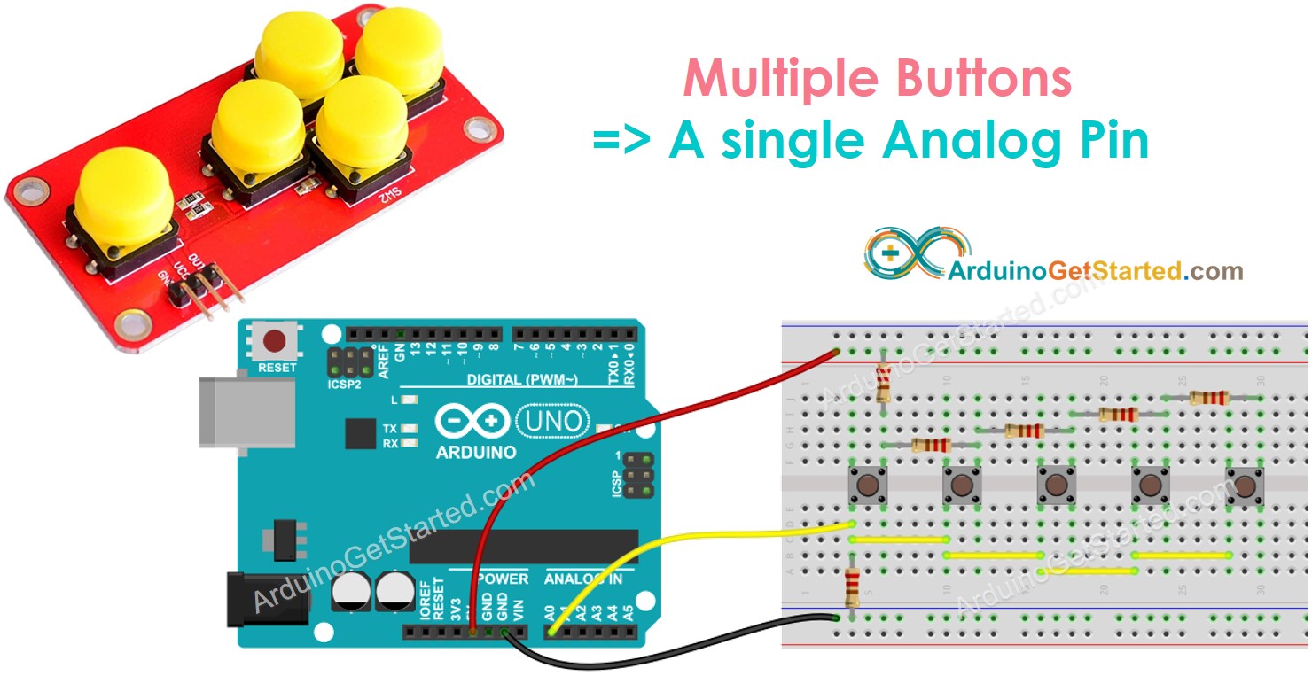
ezAnalogKeypad Library - Analog Button Array Example
When your project uses multiple buttons but IO pins are not enough ⇒ buy or build a analog button array, which connects to a single analog input pin. The analog button array allows you to use only one analog input pin. This tutorials will teach you how to the analog button array with Arduino. It also works with ESP32, ESP8266, or other platform.
Hardware Required
About ezAnalogKeypad Library
About Analog Button Array
You can build an analog buttons array by yourself or buy a ready-to-use one.
The analog buttons array connects to a single analog input pin of Arduino, ESP32, ESP8266... When a button is pressed, the analog value is changed to a specific value. This value is diffrent from each button. The ezAnalogKeypad library reads the analog value determine which button is pressed by finding a button that has a nearest value.
⇒ What we needs to do first: determine the analog value for each button when it is pressed, and also the analog value when no buttons is pressed
The analog value when a button is pressed is depending on the following factors:
- How buttons are wired
- The value of resistors
- The voltage supplies for the array of buttons
- The voltage reference of ADC
- The resolution of ADC (e.g. Arduino Uno is 10-bit ADC, ESP32 is 12-bit ADC)
⇒ The simplest way to find the analog values is run a test for callibration. By doing this way, we do not need to care about the above factors. We will learn how to do callibration in the next steps.
Wiring Diagram
- Self-made button array
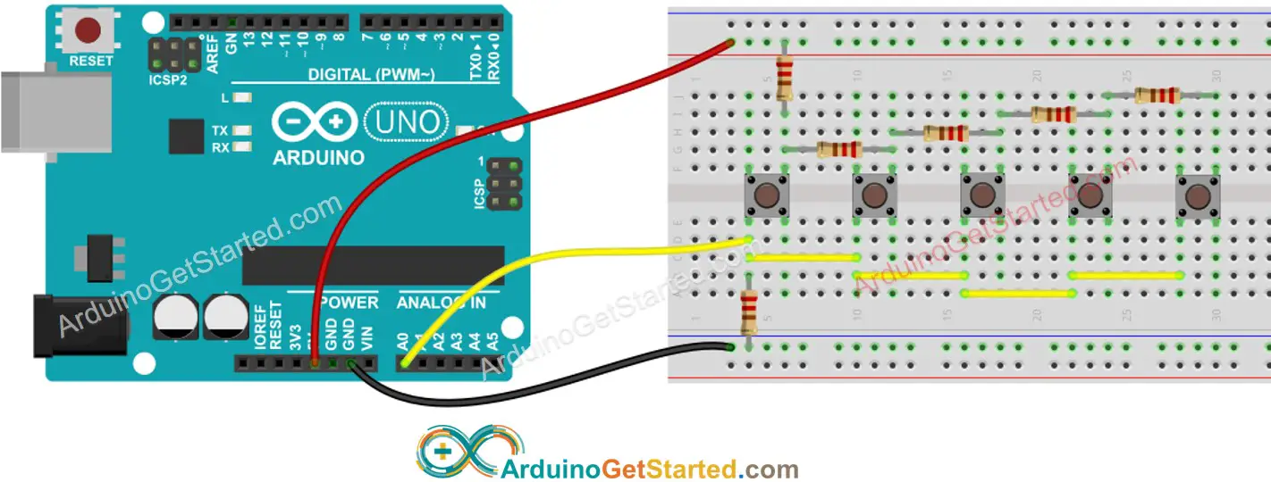
This image is created using Fritzing. Click to enlarge image
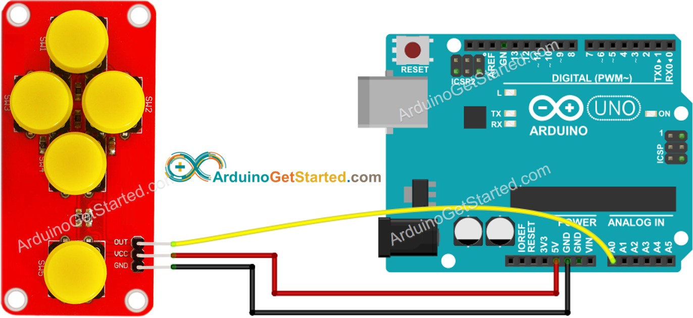
- Ready-to-use buttons module
Arduino Code
Calibration
- Install ezAnalogKeypad library. See How To
- Connect Arduino to PC via USB cable
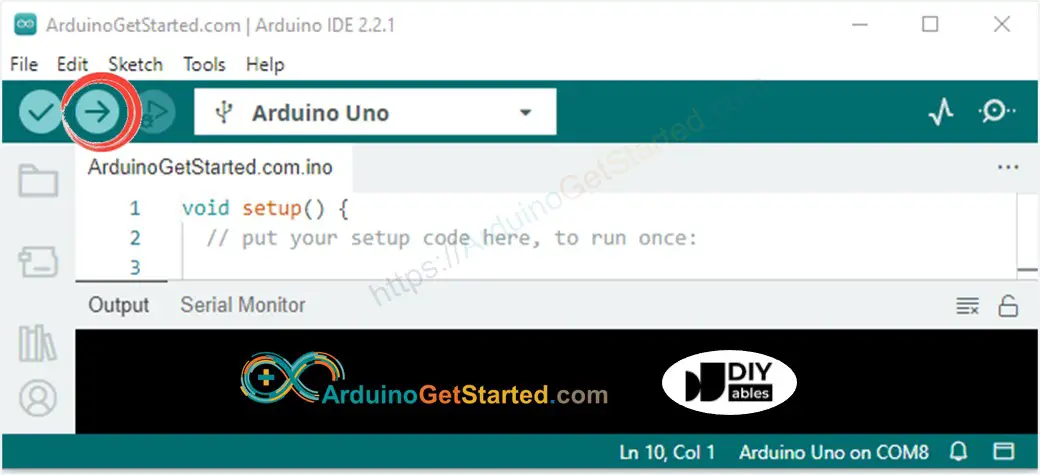
- Open Arduino IDE, select the right board and port
- On Arduino IDE, Go to File Examples ezAnalogKeypad Calibration example
- Click Upload button on Arduino IDE to upload code to Arduino
- See the output on Serial Monitor
- Write down the analog value when no button is pressed. This value will be put in keypad.setNoPressValue(value) later
- Press button one by one and write down the analog value for each button. These value will be put in keypad.registerKey(key, value) later
※ NOTE THAT:
analogValue can be fluctuated a little. You can choose a middle value. The library does not compare the analogValue equally. Instead, the library find the nearest match value.
Update the example code
- On Arduino IDE, Go to File Examples ezAnalogKeypad AnalogButtonArray example
- Update the value you wrote down in the previous callibration process into the example code
- Click Upload button on Arduino IDE to upload code to Arduino
- Press button one by one
- See the result on Serial Monitor
Code Explanation
Read the line-by-line explanation in comment lines of source code!
※ NOTE THAT:
To save memory, the maximum keys can be registered is 20 by default. If you want to increase or decrease the maximum keys (to save more memory), define ezAnalogKeypad_MAX_KEY before including the library. For example: