LDR Darkness and Light Detector Sensor Electronic Circuit
The Light Dependent Resistor (LDR) or Photo Resistor is the main component used for the darkness and light detection in real time applications. The circuit is used to automatically control the switching and turning of lights or any load depending on the brightness of ambient light. The intensity of the flow regulation across LDR increases when the light is incident on it and it can happen vice versa. The detection and switching of the light depends on the intensity of light falling on LDR.

Principle
The light dependent resistor detects the intensity of light falling on it, and results in the direction flow of current across the circuit. When the intensity of light increases the LDR resistance decreases results in the large flow current through the LED and makes it turned ON and vice versa can also happen, when there is no light incident on LDR it opposes high resistance and results in non-flow of current. Basically the change in the resistance results in the voltage across the circuit. Let’s make our project and understand the working.
Components Required:
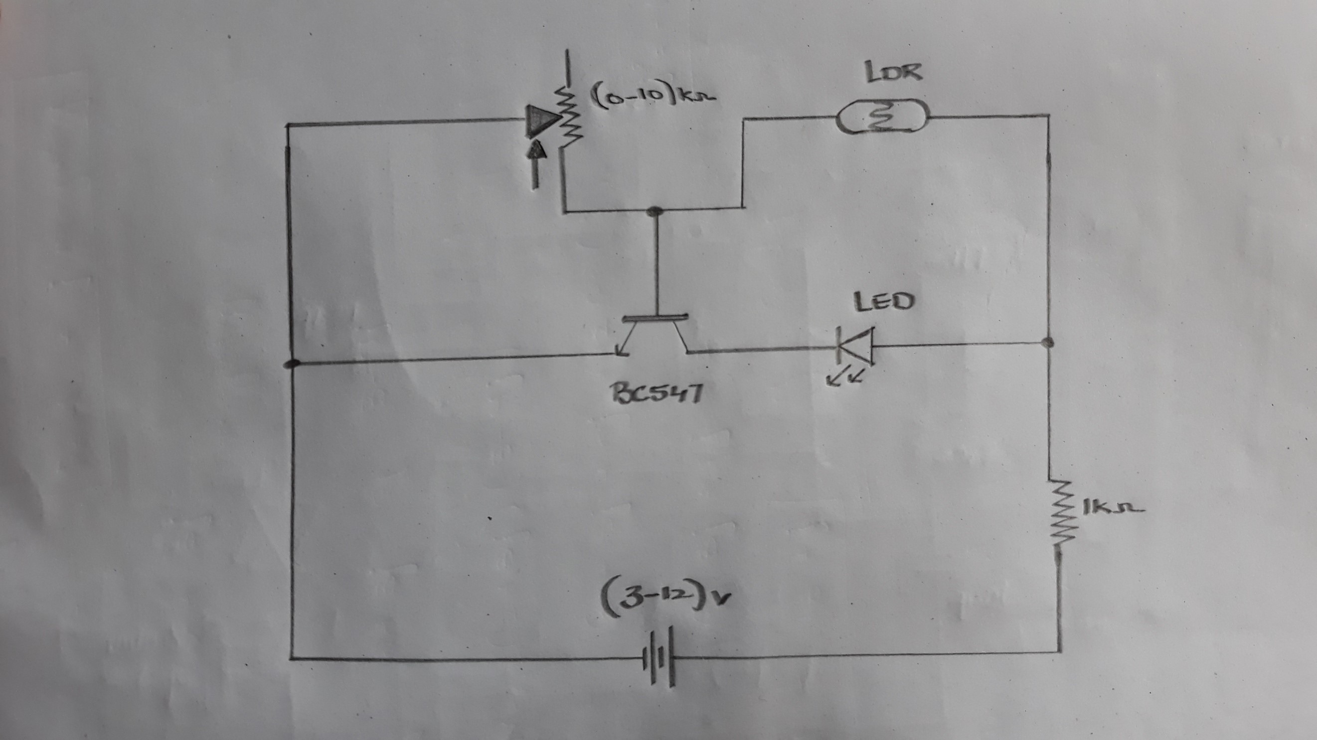
Circuit Diagram:
Procedure:
1. Place the LDR circuit on the bread board as shown in the figure below

2. Now place the LED on the bread board across the LDR

3. Connect the LDR and LED n series by connecting a jumper wire across the terminals

4. Connected the one terminal of LDR to the positive rail of the bread board

5. Now connect 470 Ohm Resistor with one of its terminal connected to the LDR and take a BC547 Transistor as shown in the figure

6. Connect the Transistor with its base connected to the LDR

7. Now connect 1k Ohm resistor with its one terminal connected to the anode of the LED and to the ground

8.Connect the power supply with its positive terminal to the positive rail of the bread board and negative terminal to the negative rail of the bred board.

9.As light is turned OFF, the incident of light falling LDR is low and LED switched OFF

10.For the fast detection output we can replace the 470 Ohm resistor with (0-10)k Ohm Potentiometer as shown in the figure.

- Connect the Potentiometer across the LDR and base of the transistor as per the circuit diagram

- Switch ON the power supply and now whenever the light incident on the LDR is high the LED turned ON and vice versa.

This is the basic principle and working operation of LDR Light and Darkness Sensor. The light incident on the LDR will determines the state of the LED.
Thank You.