Arduino Uno Pinout
Arduino Uno is the most common-used board. Let's see its pinout and how to use it.
Hardware Required
Additionally, some links direct to products from our own brand, DIYables .
Arduino Uno Pinout
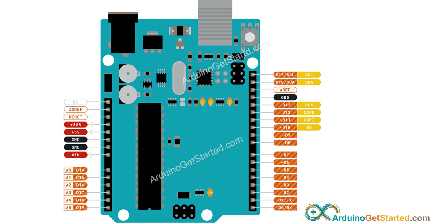
An Arduino Uno board has:
- 6 x Analog input pins. They can also be used as digital input/output pins
- 20 x digital input pins (14 x dedicated digital input + 6 x Analog input pins which can be used as digital input pins)
- 20 x digital output pins (14 x dedicated digital output + 6 x Analog input pins which can be used as digital output pins)
- 6 x PWM pins
- 1 x UART port
- 2 x I2C port (the same I2C bus)
- 1 x SPI port
- 1 x Reset pin
- 1 x 5v pin
- 1 x 3.3v pin
- 3 x GND pin
※ NOTE THAT:
For the pins are named with the prefix of 'D' (e.g. pin D1, D2 ...), It call be called without prefix of 'D', (e.g. pin 1, 2 ...)
Each pin can be used with diferent functionalities. However, at a time, each pin can be used only with one functionalitity.
Let's see how to use them
How To Use
Analog Input Pins
Applicable Pins: A0, A1, A2, A3, A4, A5
Each of analog input pins can be used as:
- Analog input pin (default)
- Digital input pin
- Digital output pin
Related functions
Example Code
Because the pin is INPUT by default, you do not need to set up it.
※ NOTE THAT:
- The pin A4 and A5 can be used for I2C communication. When they are used for I2C, do not use them as analog input.
- All analog pins can be used as digital input/output pins. See the next part for how to use it.
Digital Input Pins
Applicable Pins:
- A0, A1, A2, A3, A4, A5
- D0, D1, D2, D3, D4, D5, D6, D7, D8, D9, D10, D11, D12, D13
※ NOTE THAT:
- Pin A0, A1, A2, A3, A4, A5 have other names: , D14, D15, D16, D17, D18, D19, respectively.
Related functions
Example Code
It is the same for pin A0 to A5:
Digital Output Pins
Applicable Pins:
- A0, A1, A2, A3, A4, A5
- D0, D1, D2, D3, D4, D5, D6, D7, D8, D9, D10, D11, D12, D13
Related functions
Example Code
It is the same for pin A0 to A5:
PWM pins
Applicable Pins: D3, D5, D6, D9, D10, D11
Related functions
Example Code
UART Port
Applicable Pins: D0 (RX), D1 (TX)
See Arduino - Serial
I2C Port
Applicable Pin:
- A4 (SDA), A5 (SCL)
- D18 (SDA), D19 (SCL)
※ NOTE THAT:
- Pin A4 is internally connected to pin D18
- Pin A5 is internally connected to pin D19
Multipe I2C devices can share the same I2C bus. That is because the I2C devices are addressed by a value in data frame
SPI Port
Applicable Pin: MOSI(D11), MISO(D12), SCK(D13), SS(D10)
Please note that the SS pin is default to D10 and it can be changed
Reset Pin
If this pin is connected to GND, Arduino is reset.
See also: How to reset Arduino by programming
5v Pin, 3.3v Pin, GND Pin
See also: How to use more GND/VCC pins on Arduino
Buy Arduino
| 1 × Arduino UNO Buy on Amazon | |
| 1 × Arduino MEGA Buy on Amazon |