Arduino - RFID/NFC - Servo Motor
In this tutorial, we are going to learn how to use RFID/NFC tag to control servo motor using Arduino, It works as follows:
- If an authorized tag is tapped, Arduino rotates servo motor to 90°
- If an authorized tag is tapped again, Arduino rotates servo motor back to 0°
- The above process is repeated infinitely
This can be applied to lock/unlock cabinet, drawer, door, or open/clock the pet feeder...
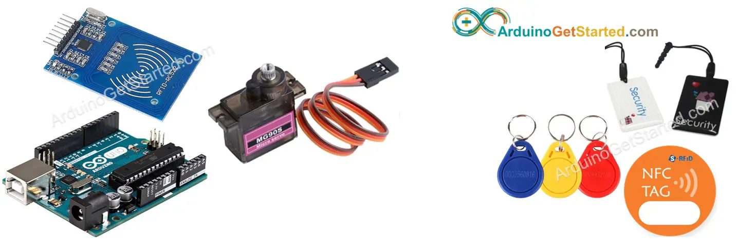
Hardware Required
Or you can buy the following kits:
| 1 | × | DIYables STEM V3 Starter Kit (Arduino included) | |
| 1 | × | DIYables Sensor Kit (18 sensors/displays) |
Additionally, some links direct to products from our own brand, DIYables .
Buy Note: When using multiple servo motors, we recommend the PCA9685 16 Channel PWM Servo Driver Module to save MCU pins and make wiring easier.
About RFID/NFC RC522 Module and Servo Motor
If you do not know about RFID/NFC RC522 Module and Servo Motor (pinout, how it works, how to program ...), learn about them in the following tutorials:
- Arduino - RFID/NFC RC522 tutorial
- Arduino - Servo Motor tutorial
How It Works
- The UIDs of some RFID/NFC tags are preset in Arduino code
- User taps an RFID/NFC tag on RFID/NFC reader
- The reader reads UID from the tag.
- Arduino gets the UID from the reader
- Arduino compares the read UID with the predefined UIDs
- If the UID is matched with one of the predefined UIDs, Arduino controls servo motor to 90°.
- If the tag is tapped again, Arduino controls servo motor back to 0°
- This process is repeated infinitely.
Wiring Diagram
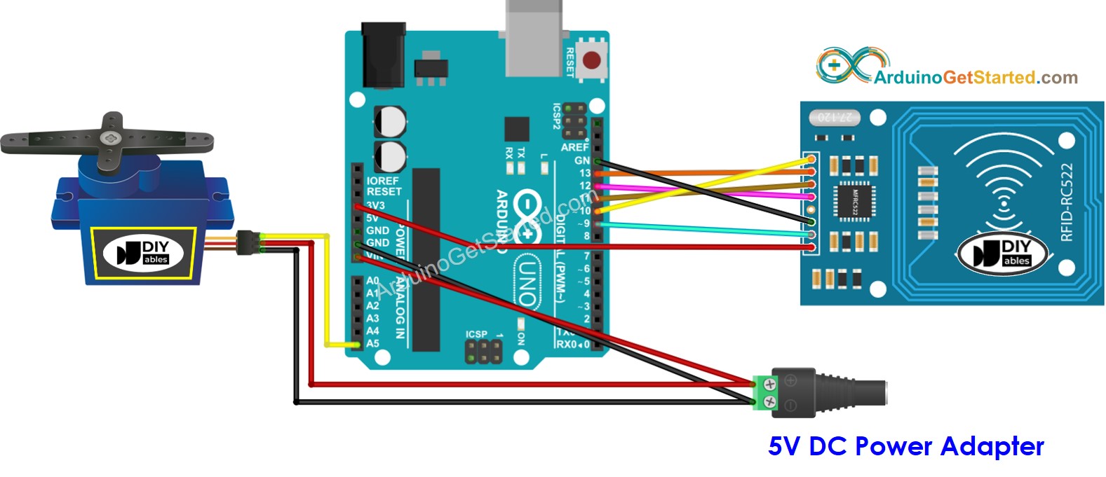
This image is created using Fritzing. Click to enlarge image
In above wiring diagram, a single 5V addapter supplies power to Arduino directly, to servo motor directly, and RC522 module (indirectly via 3.3V pin of Arduino).
To simplify the process, the pins of the RC522 module are directly connected to the pins of the Arduino. However, this can cause the Arduino to stop functioning correctly in certain cases as the output pins of the Arduino produce a voltage of 5V, while the pins of the RC522 module function normally at a voltage of 3.3V. Consequently, it is advisable to regulate the voltage between the pins of the Arduino and those of the RC522 module. For further details, please refer to the Arduino - RFID RC522 tutorial. The diagram below depicts how to regulate 5V to 3.3V using resistors:
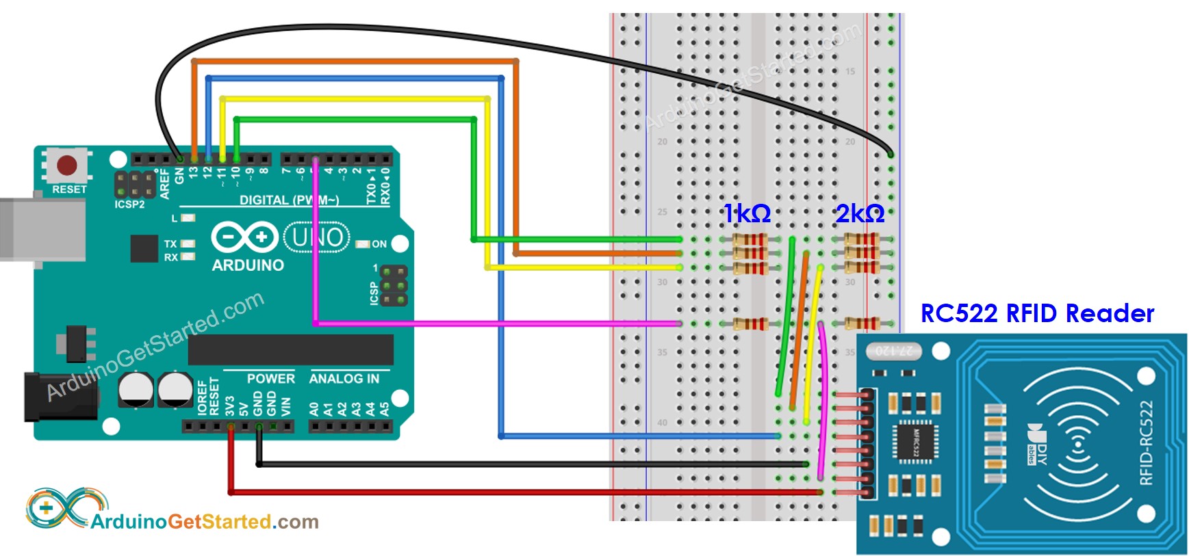
This image is created using Fritzing. Click to enlarge image
※ NOTE THAT:
The order of pins can vary according to manufacturers. ALWAYS use the labels printed on the module. The above image shows the pinout of the modules from DIYables manufacturer.
Wiring table of RFID/NFC RC522 Module
| RFID/NFC RC522 | Arduino |
|---|---|
| SS | → 10 |
| SCK | → 13 |
| MOSI | → 11 |
| MISO | → 12 |
| IRQ(not connected) | |
| GND | → GND |
| RST | → 9 |
| VCC | → 3.3V |
Wiring table of Servo Motor
| Servo Motor | Arduino | 5V DC Adapter |
|---|---|---|
| VCC (red) | → positive | |
| GND (brown) | → negative | |
| SIG (yellow) | → A5 |
Wiring table of 5V DC Adapter
| 5V DC Adapter | Servo Motor | Arduino |
|---|---|---|
| Positive | → VCC | |
| Positive | -> Vin | |
| Negative | → GND | |
| Negative | → GND |
Arduino Code - Single RFID/NFC Tag
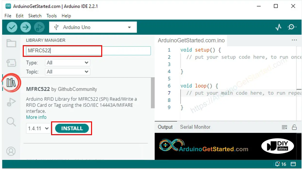
Quick Steps
- Navigate to the Libraries icon on the left bar of the Arduino IDE.
- Search “MFRC522”, then find the library by GithubCommunity
- Click Install button to install MFRC522 library.
Because UID is usually not printed on RFID/NFC tag, The first step we need to do is to find out the tag's UID. This can be done by:
- Copy the above code and open with Arduino IDE
- Click Upload button on Arduino IDE to upload code to Arduino
- Open Serial Monitor
- Tap an RFID/NFC tag on RFID-RC522 module
- Get UID on Serial Monitor
After having UID:
- Update UID in the line 20 of the above code. For example, change byte authorizedUID[4] = {0xFF, 0xFF, 0xFF, 0xFF}; TO byte authorizedUID[4] = {0x3A, 0xC9, 0x6A, 0xCB};
- Upload the code to Arduino again
- Tap an RFID/NFC tag on RFID-RC522 module
- You will see the servo motor rotate to 90°
- See output on Serial Monitor
- Tap the same RFID/NFC tag on RFID-RC522 module again
- You will see the servo motor rotate to 0°
- See output on Serial Monitor
- Tap another RFID/NFC tag on RFID-RC522 module
- See output on Serial Monitor
Video Tutorial
We are considering to make the video tutorials. If you think the video tutorials are essential, please subscribe to our YouTube channel to give us motivation for making the videos.