Arduino - Traffic Light
In this tutorial, we are going to learn how to use Arduino control the traffic light module. In detail, we will learn:
How to connect the traffic light module to Arduino
How to program Arduino to control RGB traffic light module
How to program Arduino to control RGB traffic light module without using delay() function
Or you can buy the following kits:
Disclosure: Some links in this section are Amazon affiliate links. If you make a purchase through these links, we may earn a commission at no extra cost to you.
Additionally, some links direct to products from our own brand,
DIYables .
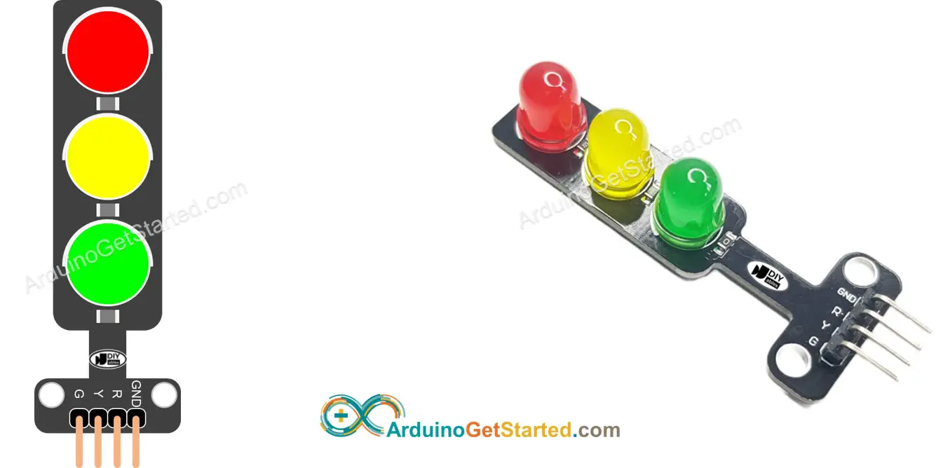
A traffic light module includes 4 pins:
GND pin: The ground pin, connect this pin to GND of Arduino.
R pin: The pin to control the red light, connect this pin to a digital output of Arduino.
Y pin: The pin to control the yellow light, connect this pin to a digital output of Arduino.
G pin: The pin to control the green light, connect this pin to a digital output of Arduino.
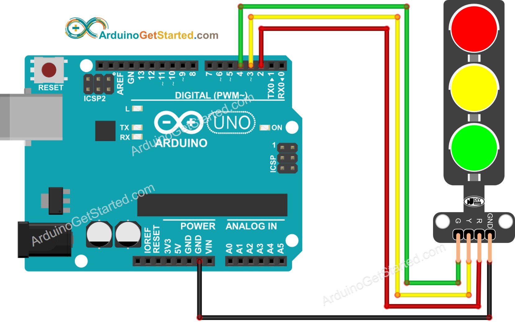
This image is created using Fritzing. Click to enlarge image
Configure an Arduino's pins to the digital output mode by using
pinMode() function
pinMode(PIN_RED, OUTPUT);
pinMode(PIN_YELLOW, OUTPUT);
pinMode(PIN_GREEN, OUTPUT);
digitalWrite(PIN_RED, HIGH);
digitalWrite(PIN_YELLOW, LOW);
digitalWrite(PIN_GREEN, LOW);
delay(RED_TIME);
#define PIN_RED 2
#define PIN_YELLOW 3
#define PIN_GREEN 4
#define RED_TIME 4000
#define YELLOW_TIME 4000
#define GREEN_TIME 4000
void setup() {
pinMode(PIN_RED, OUTPUT);
pinMode(PIN_YELLOW, OUTPUT);
pinMode(PIN_GREEN, OUTPUT);
}
void loop() {
digitalWrite(PIN_RED, HIGH);
digitalWrite(PIN_YELLOW, LOW);
digitalWrite(PIN_GREEN, LOW);
delay(RED_TIME);
digitalWrite(PIN_RED, LOW);
digitalWrite(PIN_YELLOW, HIGH);
digitalWrite(PIN_GREEN, LOW);
delay(YELLOW_TIME);
digitalWrite(PIN_RED, LOW);
digitalWrite(PIN_YELLOW, LOW);
digitalWrite(PIN_GREEN, HIGH);
delay(GREEN_TIME);
}
Copy the above code and open with Arduino IDE
Click Upload button on Arduino IDE to upload code to Arduino
Check out the traffic light module
image source: diyables.io
It's important to note that the exact workings of a traffic light can vary depending on the specific design and technology used in different regions and intersections. The principles described above provide a general understanding of how traffic lights operate to manage traffic and enhance safety on the roads.
The code above demonstrates individual light control. Now, let's enhance the code for better optimization.
#define PIN_RED 2
#define PIN_YELLOW 3
#define PIN_GREEN 4
#define RED_TIME 2000
#define YELLOW_TIME 1000
#define GREEN_TIME 2000
#define RED 0
#define YELLOW 1
#define GREEN 2
const int pins[] = { PIN_RED, PIN_YELLOW, PIN_GREEN };
const int times[] = { RED_TIME, YELLOW_TIME, GREEN_TIME };
void setup() {
pinMode(PIN_RED, OUTPUT);
pinMode(PIN_YELLOW, OUTPUT);
pinMode(PIN_GREEN, OUTPUT);
}
void loop() {
trafic_light_on(RED);
delay(times[RED]);
trafic_light_on(YELLOW);
delay(times[YELLOW]);
trafic_light_on(GREEN);
delay(times[GREEN]);
}
void trafic_light_on(int light) {
for (int i = RED; i <= GREEN; i++) {
if (i == light)
digitalWrite(pins[i], HIGH);
else
digitalWrite(pins[i], LOW);
}
}
#define PIN_RED 2
#define PIN_YELLOW 3
#define PIN_GREEN 4
#define RED_TIME 2000
#define YELLOW_TIME 1000
#define GREEN_TIME 2000
#define RED 0
#define YELLOW 1
#define GREEN 2
const int pins[] = {PIN_RED, PIN_YELLOW, PIN_GREEN};
const int times[] = {RED_TIME, YELLOW_TIME, GREEN_TIME};
void setup() {
pinMode(PIN_RED, OUTPUT);
pinMode(PIN_YELLOW, OUTPUT);
pinMode(PIN_GREEN, OUTPUT);
}
void loop() {
for (int light = RED; light <= GREEN; light ++) {
trafic_light_on(light);
delay(times[light]);
}
}
void trafic_light_on(int light) {
for (int i = RED; i <= GREEN; i ++) {
if (i == light)
digitalWrite(pins[i], HIGH);
else
digitalWrite(pins[i], LOW);
}
}
#define PIN_RED 2
#define PIN_YELLOW 3
#define PIN_GREEN 4
#define RED_TIME 2000
#define YELLOW_TIME 1000
#define GREEN_TIME 2000
#define RED 0
#define YELLOW 1
#define GREEN 2
const int pins[] = { PIN_RED, PIN_YELLOW, PIN_GREEN };
const int times[] = { RED_TIME, YELLOW_TIME, GREEN_TIME };
unsigned long last_time = 0;
int light = RED;
void setup() {
pinMode(PIN_RED, OUTPUT);
pinMode(PIN_YELLOW, OUTPUT);
pinMode(PIN_GREEN, OUTPUT);
trafic_light_on(light);
last_time = millis();
}
void loop() {
if ((millis() - last_time) > times[light]) {
light++;
if (light >= 3)
light = RED;
trafic_light_on(light);
last_time = millis();
}
}
void trafic_light_on(int light) {
for (int i = RED; i <= GREEN; i++) {
if (i == light)
digitalWrite(pins[i], HIGH);
else
digitalWrite(pins[i], LOW);
}
}
We are considering to make the video tutorials. If you think the video tutorials are essential, please subscribe to our YouTube channel to give us motivation for making the videos.
※ OUR MESSAGES
You can share the link of this tutorial anywhere. Howerver, please do not copy the content to share on other websites. We took a lot of time and effort to create the content of this tutorial, please respect our work!