Arduino - Flame Sensor
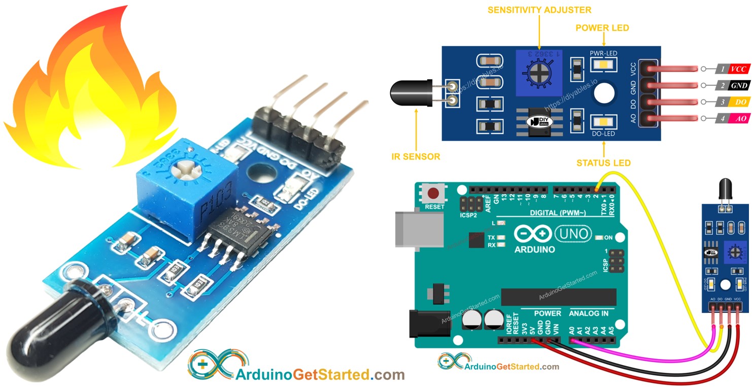
The flame sensor is capable of detecting and measuring infrared level emited from the flame, It can be used to detect fire. It is also called infrared flame sensor, or fire sensor. The infrared flame sensor provides two outputs: a digital output (LOW/HIGH) and an analog output.
In this tutorial, we will learn how to use an Arduino and an flame sensor to detect and measure the flame and fire. Specifically, we will cover the following:
- How to connect the flame sensor to an Arduino.
- How to program the Arduino to detect the flame and fire by reading the digital signal from the flame sensor.
- How to program the Arduino to measure the flame level by reading the analog signal from the flame sensor.
Afterward, you can modify the code to activate a warning horn (via a relay) when it detects fire.
Hardware Required
Or you can buy the following kits:
| 1 | × | DIYables STEM V3 Starter Kit (Arduino included) | |
| 1 | × | DIYables Sensor Kit (18 sensors/displays) |
Additionally, some links direct to products from our own brand, DIYables .
About Flame Sensor
The infrared flame sensor can be utilized to detect the presence of flame or measure the infrared level emited by the flame. Therefore, The flame sensor can be used to detect the fire. The flame sensor provides two options via a digital output pin and analog output pin.
The infrared flame sensors are designed to be selective in the wavelengths of infrared radiation they detect, focusing on the specific wavelengths associated with flames. They are engineered to minimize the likelihood of false alarms from other sources of infrared radiation, such as human body heat or artificial lighting. However, like any sensor, they have limitations, and under certain conditions, they might be susceptible to false positives or false negatives.
Pinout
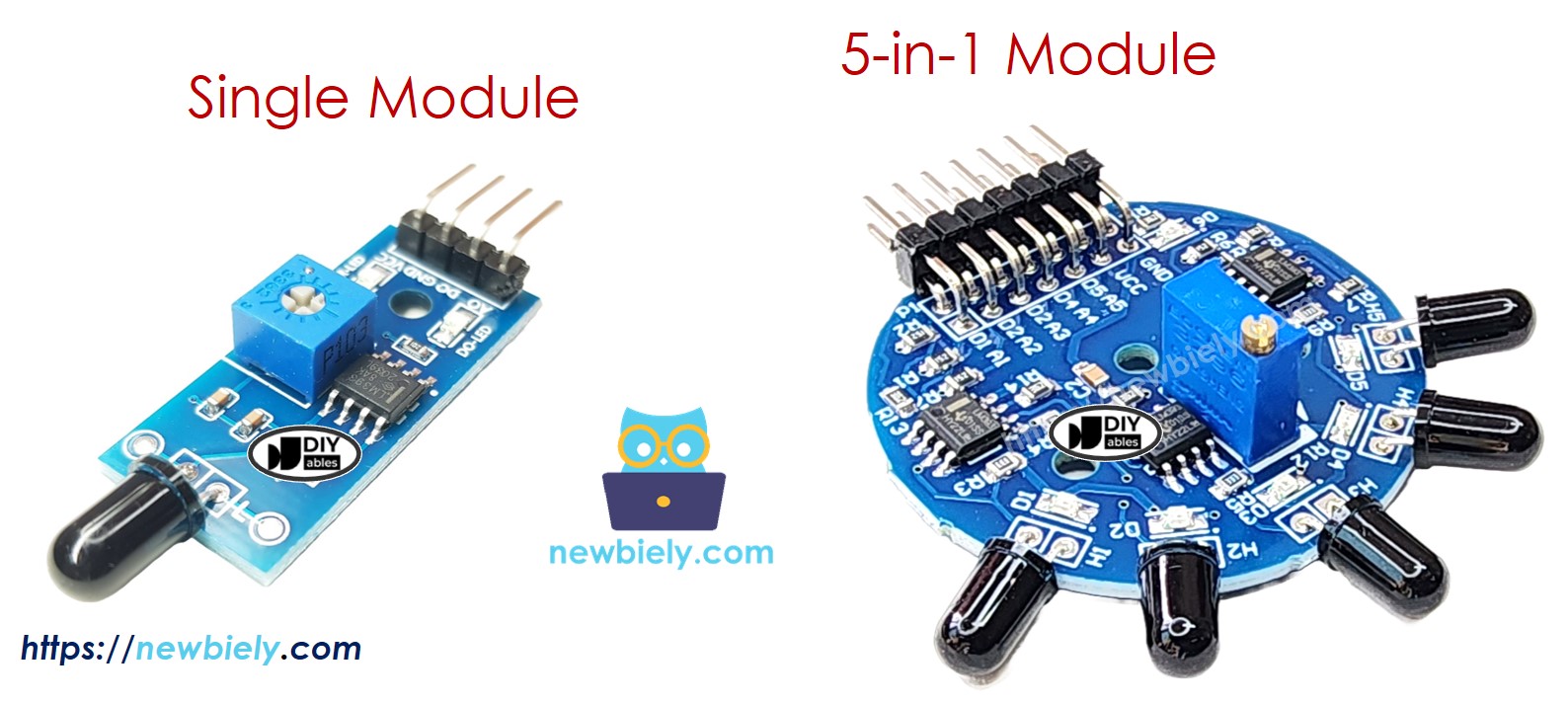
There are two types of flame sensor modules available:
A single flame sensor includes four pins:
- VCC pin: It needs to be connected to VCC (3.3V to 5V).
- GND pin: It needs to be connected to GND (0V).
- DO pin: It is a digital output pin. It is HIGH if the flame is not detected and LOW if detected. The threshold value for flame detection can be adjusted using a built-in potentiometer.
- AO pin: It is an analog output pin. The output value decreases as the infraed level is decreased, and it increases as infraed level is increased.
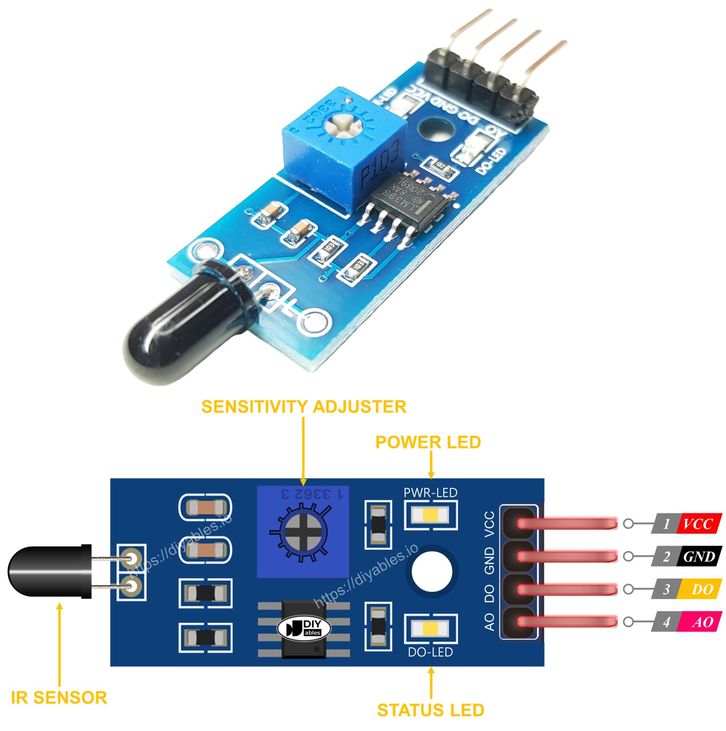
Furthermore, it has two LED indicators:
- One PWR-LED indicator for power.
- One DO-LED indicator for the flame state on the DO pin: it is on when flame is present.
The 5-in-1 flame sensor integrates five individual flame sensors on a single PCB. While they share the same potentiometer, VCC, and GND, each sensor’s DO (Digital Output) and AI (Analog Input) pins function independently. Additionally, each sensor is oriented in a different direction, which effectively broadens the overall detection range.
How It Works
For the DO pin:
- The module has a built-in potentiometer for setting the infrared threshold (sensitivity).
- When the infrared intensity is above the threshold value, the flame is detected, the output pin of the sensor is LOW, and the DO-LED is on.
- When the infrared intensity is below the threshold value, the flame is NOT detected, the output pin of the sensor is HIGH, and the DO-LED is off.
For the AO pin:
- The higher the infrared intensity in the surrounding environment, the higher the value read from the AO pin.
- The lower the infrared intensity in the surrounding environment, the lower the value read from the AO pin.
Note that the potentiometer does not affect the value on the AO pin.
Wiring Diagram
Since the flame sensor module has two outputs, you can choose to use one or both of them, depending on what you need.
- The wiring diagram between Arduino and the flame sensor when using DO only.
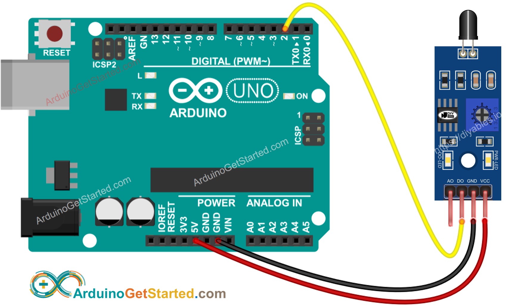
This image is created using Fritzing. Click to enlarge image
- The wiring diagram between Arduino and the flame sensor when using AO only.
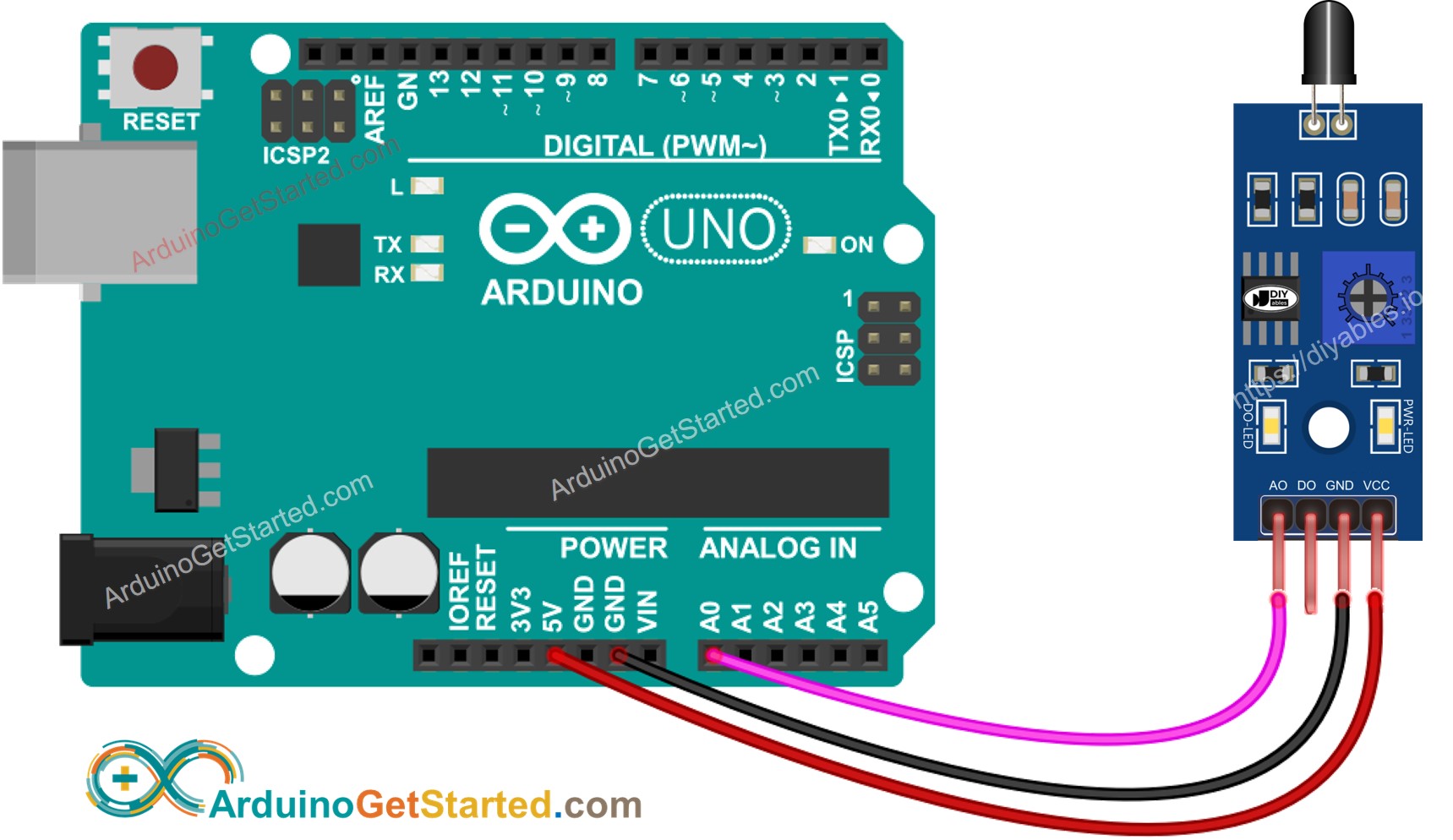
This image is created using Fritzing. Click to enlarge image
- The wiring diagram between Arduino and the flame sensor when using both AO an DO.
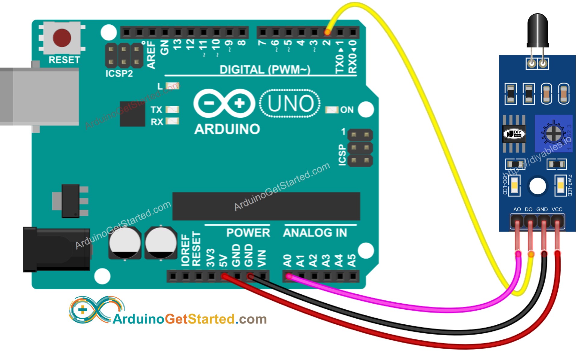
This image is created using Fritzing. Click to enlarge image
Arduino Code - Read value from DO pin
Quick Steps
- Copy the above code and open with Arduino IDE
- Click Upload button on Arduino IDE to upload code to Arduino
- Direct the flame sensor to a flame.
- See the result on Serial Monitor.
Please keep in mind that if you notice the LED status remaining on constantly or off even when the sensor faces to a flame, you can adjust the potentiometer to fine-tune the sensitivity of the sensor.
Arduino Code - Read value from AO pin
Quick Steps
- Copy the above code and open with Arduino IDE
- Click Upload button on Arduino IDE to upload code to Arduino
- Direct the flame sensor to a flame.
- See the result on Serial Monitor.
Video Tutorial
We are considering to make the video tutorials. If you think the video tutorials are essential, please subscribe to our YouTube channel to give us motivation for making the videos.