Arduino - 2-Channel Relay Module
If we need to control two high-voltage devices like pumps, fans, or actuators, we have two options. One option is to use multiple relay modules, but there's an easier way. We can use a 2-channel relay module, which is a single board with two relays built into it. This simplifies the setup and makes it more convenient to control both devices.
Before learning how to use Arduino to control the 2-channel relay module, let's compare a 2-channel relay module to two separate 1-channel relay modules:
- The wiring for a 2-channel relay module is simpler.
- A 2-channel relay module takes up less space.
- Using a 2-channel relay module is more cost-effective.
- The programming required is the same for both options.
Hardware Required
Or you can buy the following kits:
| 1 | × | DIYables STEM V3 Starter Kit (Arduino included) | |
| 1 | × | DIYables Sensor Kit (18 sensors/displays) |
Additionally, some links direct to products from our own brand, DIYables .
About 2-Channel Relay Module
Pinout
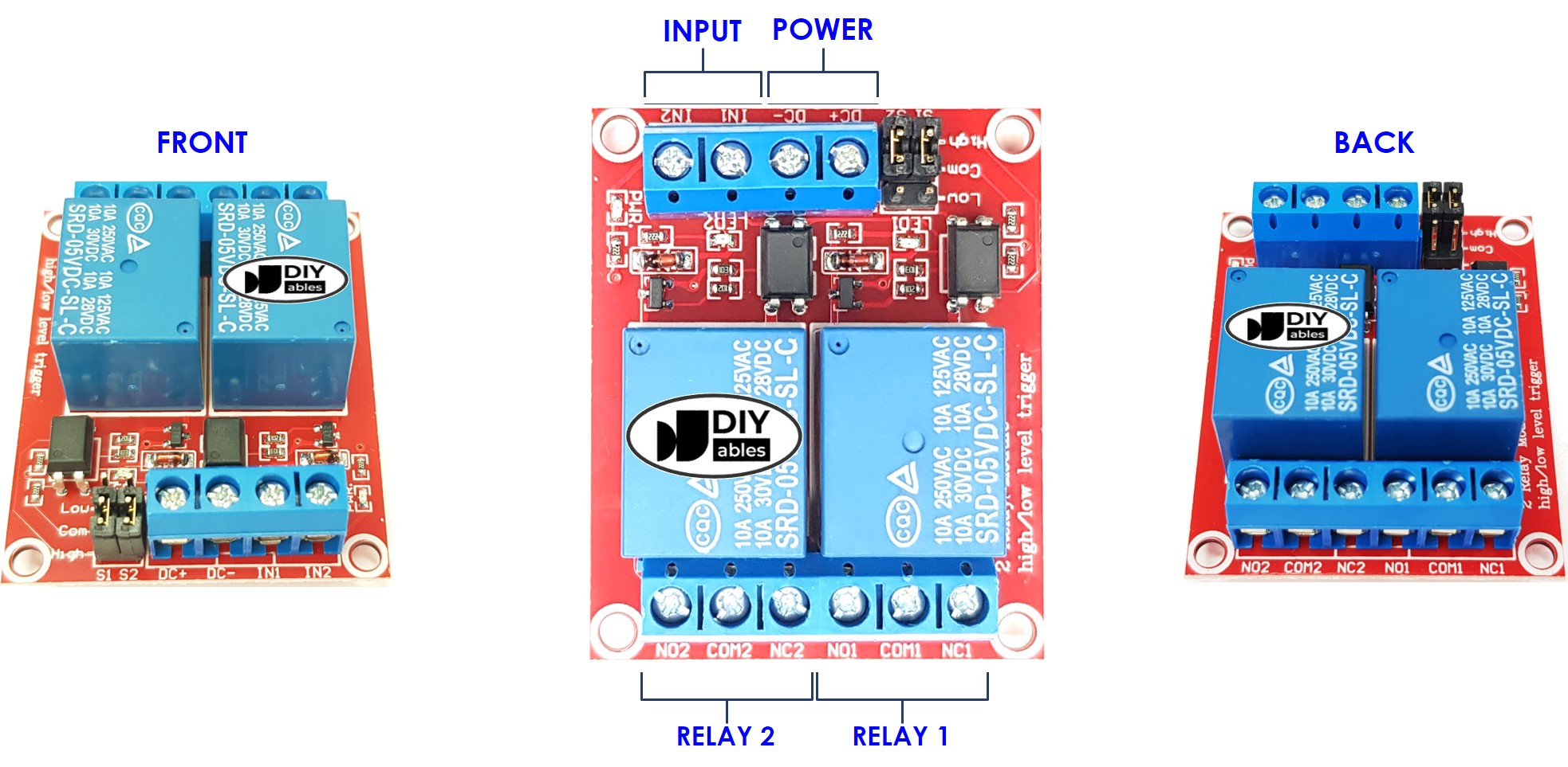
A 2-channel relay module has the following pins:
- Power pins for relay boards
- DC+: connect this pin to 5V pin of power supply
- DC-: connect this pin to the GND pin of the power supply and also to the GND pin of the Arduino
- Signal pins:
- IN1: this pin receives the control signal from Arduino to control relay 1 on the module
- IN2: this pin receives the control signal from Arduino to control relay 2 on the module
- Output pins: NCx (normally closed pin), NOx (normally open pin), COMx (common pin),
- NC1, NO1, COM1: These pins connect to a high-voltage device that is controlled by relay 1
- NC2, NO2, COM2: These pins connect to a high-voltage device that is controlled by relay 2
- How to connect relay to high-voltage devices.
- The terms normally closed and normally open
- The terms low level trigger and high level trigger
- How to control relay using Arduino
It also has 2 jumpers to select between the low level trigger and the high level trigger for each relay individually.
If you want to learn the basic of relay, you can check out the Arduino - Relay tutorial. It provides detailed information on:
Wiring Diagram
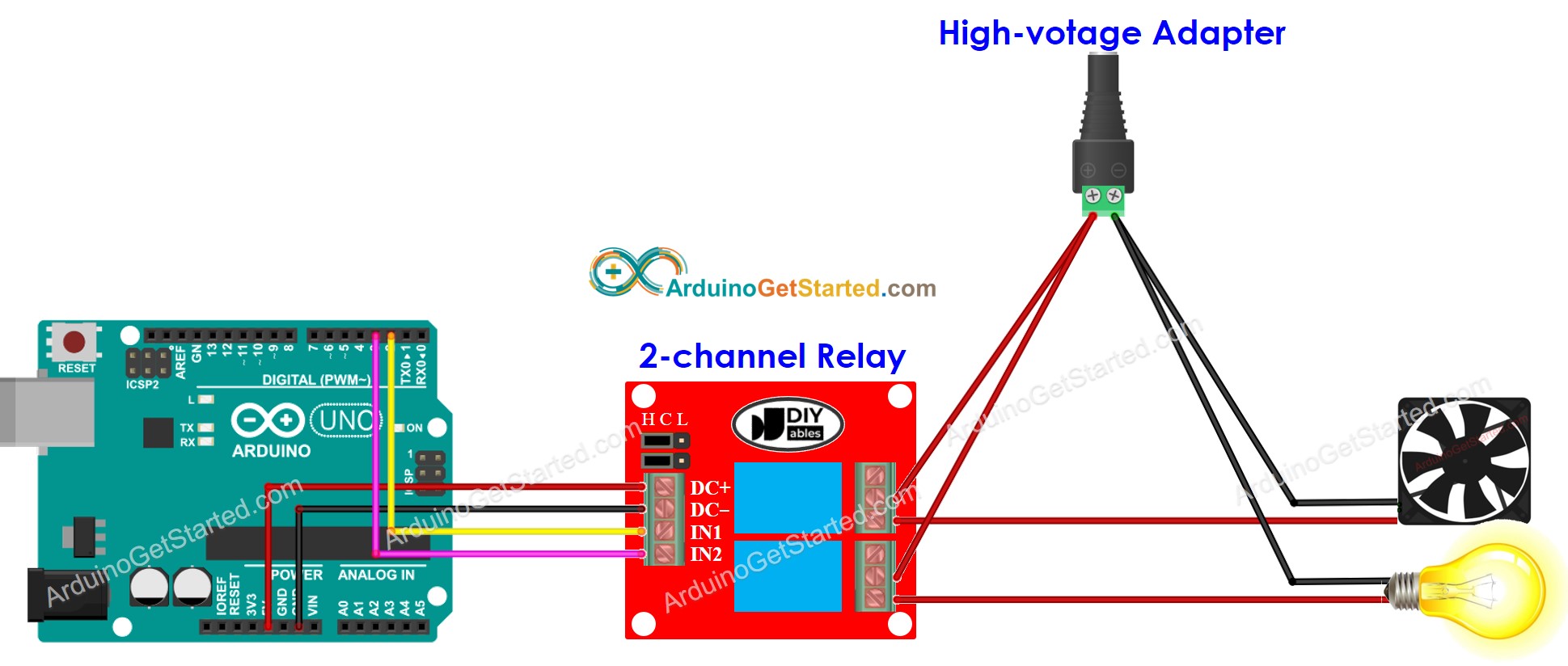
This image is created using Fritzing. Click to enlarge image
If you intend to power other components using the 5V pins, it is possible that the relay module may not receive sufficient power. Consequently, it is necessary to utilize an external 5V power source specifically for the module.
So, we need to use three types of power sources:
- A 5V power adapter for Arduino
- A 5V power adapter for the 2-channel relay module
- One or several higher-voltage power adapters (12VDC, 24VDC, 48VDC, 220AC...) for things that are controlled by the 2-channel relay module
The below is the wiring diagram with three power sources. Power supply for Arduino (not included in the image) can be via either USB cable or power jack.
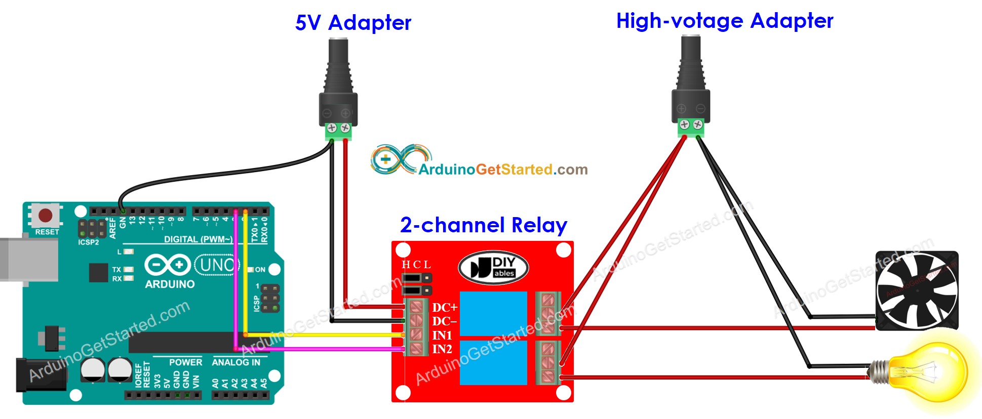
This image is created using Fritzing. Click to enlarge image
We can cut down on the number of power adapters by using just one 5V power supply for both the Arduino and the 2-channel relay module.
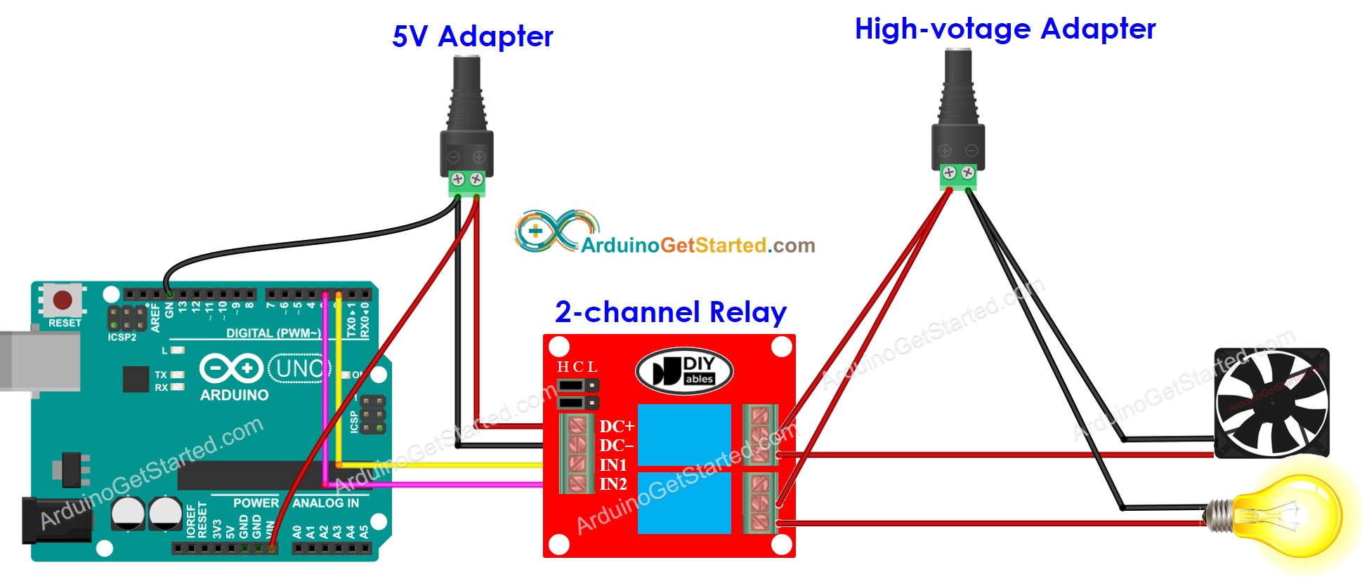
This image is created using Fritzing. Click to enlarge image
※ NOTE THAT:
If 2 devices that are controlled by a 2-channel relay module use the same voltage, we can use a single high-voltage power adapter for all. However, if they use different voltages, we can use different high-voltage power adapters independently.
How To Program For 2-Channel Relay Module
- Initializes the Arduino pin to the digital output mode by using pinMode() function.
- Control the relay's state by using digitalWrite() function.
Arduino Code
Quick Steps
- Copy the above code and open with Arduino IDE
- Click Upload button on Arduino IDE to upload code to Arduino
- Listen the click sound on relays.
- See the result on Serial Monitor.
Video Tutorial
We are considering to make the video tutorials. If you think the video tutorials are essential, please subscribe to our YouTube channel to give us motivation for making the videos.