Arduino - Rotary Encoder LED

In this tutorial, We are going to learn how to program Arduino to control the brightness of a LED according to the rotary encoder's output value.

Hardware Required

1×Arduino UNO or Genuino UNO
1×USB 2.0 cable type A/B (for USB-A PC)
1×USB 2.0 cable type C/B (for USB-C PC)
1×Rotary Encoder
1×LED
1×220 ohm resistor
1×Breadboard
1×Jumper Wires
1×(Recommended) Screw Terminal Block Shield for Arduino Uno
1×(Recommended) Breadboard Shield For Arduino Uno
1×(Recommended) Enclosure For Arduino Uno

Or you can buy the following sensor kits:

1×DIYables Sensor Kit (30 sensors/displays)
1×DIYables Sensor Kit (18 sensors/displays)
Disclosure: Some links in this section are Amazon affiliate links. If you make a purchase through these links, we may earn a commission at no extra cost to you.
Additionally, some links direct to products from our own brand, DIYables.

About LED and Rotary Encoder

If you do not know about LED and rotary encoder (pinout, how it works, how to program ...), learn about them in the following tutorials:

Wiring Diagram
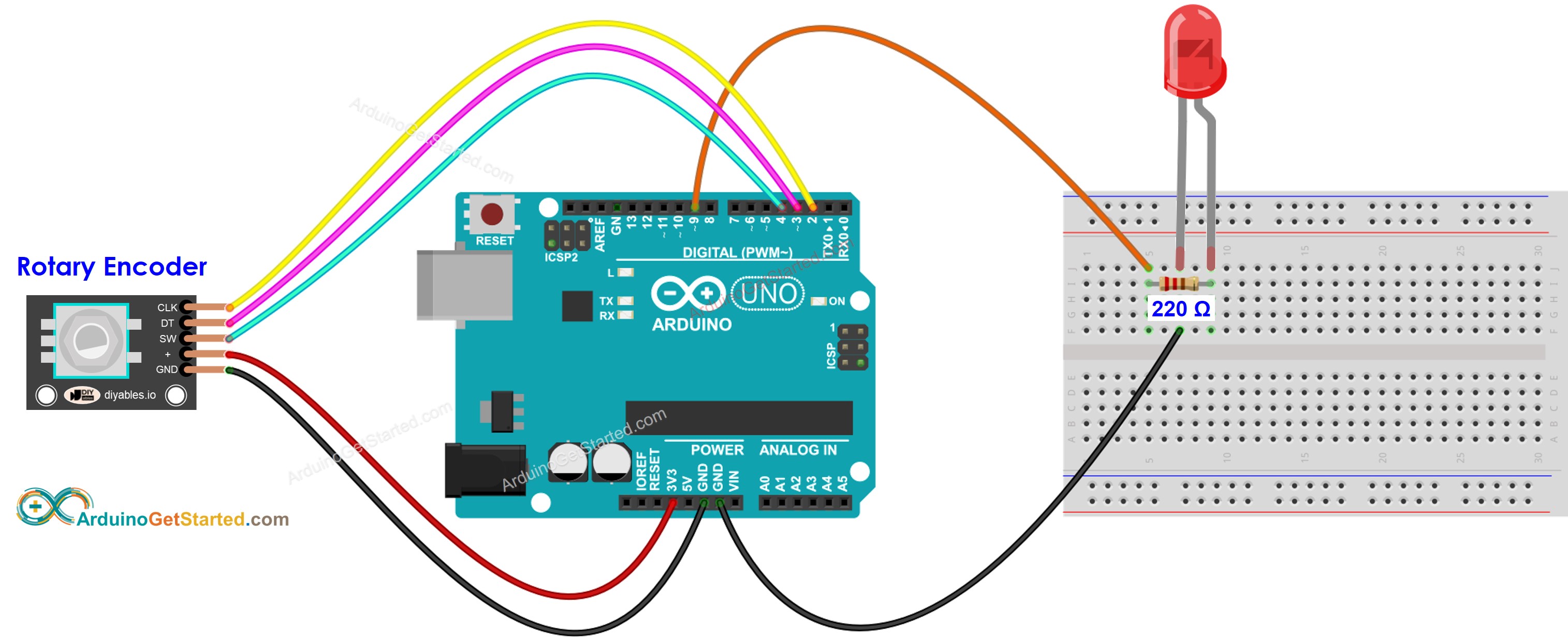
Arduino Rotary Encoder LED Wiring Diagram

This image is created using Fritzing. Click to enlarge image

Arduino Code

/* * Created by ArduinoGetStarted.com * * This example code is in the public domain * * Tutorial page: https://arduinogetstarted.com/tutorials/arduino-rotary-encoder-led */ #include <Servo.h> #define CLK_PIN 2 #define DT_PIN 3 #define SW_PIN 4 #define LED_PIN 9 #define DIRECTION_CW 0 // clockwise direction #define DIRECTION_CCW 1 // counter-clockwise direction int counter = 0; int direction = DIRECTION_CW; int CLK_state; int prev_CLK_state; int brightness = 125; // middle value void setup() { Serial.begin(9600); // configure encoder pins as inputs pinMode(CLK_PIN, INPUT); pinMode(DT_PIN, INPUT); // read the initial state of the rotary encoder's CLK pin prev_CLK_state = digitalRead(CLK_PIN); pinMode(LED_PIN, OUTPUT); } void loop() { // read the current state of the rotary encoder's CLK pin CLK_state = digitalRead(CLK_PIN); // If the state of CLK is changed, then pulse occurred // React to only the rising edge (from LOW to HIGH) to avoid double count if (CLK_state != prev_CLK_state && CLK_state == HIGH) { // if the DT state is HIGH // the encoder is rotating in counter-clockwise direction => decrease the counter if (digitalRead(DT_PIN) == HIGH) { direction = DIRECTION_CCW; counter--; brightness -= 10; // you can change this value } else { // the encoder is rotating in clockwise direction => increase the counter direction = DIRECTION_CW; counter++; brightness += 10; // you can change this value } if (brightness < 0) brightness = 0; else if (brightness > 255) brightness = 255; // sets the brightness of LED according to the counter analogWrite(LED_PIN, brightness); Serial.print("COUNTER: "); Serial.print(counter); Serial.print(" | BRIGHTNESS: "); Serial.println(brightness); } // save last CLK state prev_CLK_state = CLK_state; }

Quick Steps

  • Connect Arduino to PC via USB cable
  • Open Arduino IDE, select the right board and port
  • Copy the above code and open with Arduino IDE
  • Click Upload button on Arduino IDE to upload code to Arduino
  • Open Serial Monitor
  • Rotate the rotary encoder
  • See the LED's brightness
  • See the result on Serial Monitor
COM6
Send
COUNTER: 1 | BRIGHTNESS: 135 COUNTER: 2 | BRIGHTNESS: 145 COUNTER: 3 | BRIGHTNESS: 155 COUNTER: 4 | BRIGHTNESS: 165 COUNTER: 5 | BRIGHTNESS: 175 COUNTER: 6 | BRIGHTNESS: 185 COUNTER: 7 | BRIGHTNESS: 195
Autoscroll Show timestamp
Clear output
9600 baud  
Newline  

Code Explanation

Read the line-by-line explanation in comment lines of source code!

Video Tutorial

We are considering to make the video tutorials. If you think the video tutorials are essential, please subscribe to our YouTube channel to give us motivation for making the videos.

The Best Arduino Starter Kit

※ OUR MESSAGES