Arduino - RFID/NFC
In this tutorial, we are going to learn how to use RFID/NFC with Arduino. The RFID/NFC system includes two components: reader and tag. There are two popular RFID/NFC readers: RC522 and PN532 RFID/NFC reader. This tutorial focuses on RC522 RFID/NFC reader. PN532 RFID/NFC reader will be presented in an upcoming tutorial.
RC522 RFID/NFC reader (also called RFID-RC522 Module) can:
- Read the UID of RFID/NFC tag
- Change the UID of RFID/NFC tag (only if the tag is UID-writable)
- Write data to RFID/NFC tag
- Read data from RFID/NFC tag
In above capabilities, for Arduino, reading the UID is the most widely-used. This tutorial focuses on reading the UID of RFID/NFC tag. The other will be present in next tutorials
Hardware Required
Or you can buy the following kits:
| 1 | × | DIYables STEM V3 Starter Kit (Arduino included) | |
| 1 | × | DIYables Sensor Kit (18 sensors/displays) |
Additionally, some links direct to products from our own brand, DIYables .
About RFID-RC522 Module
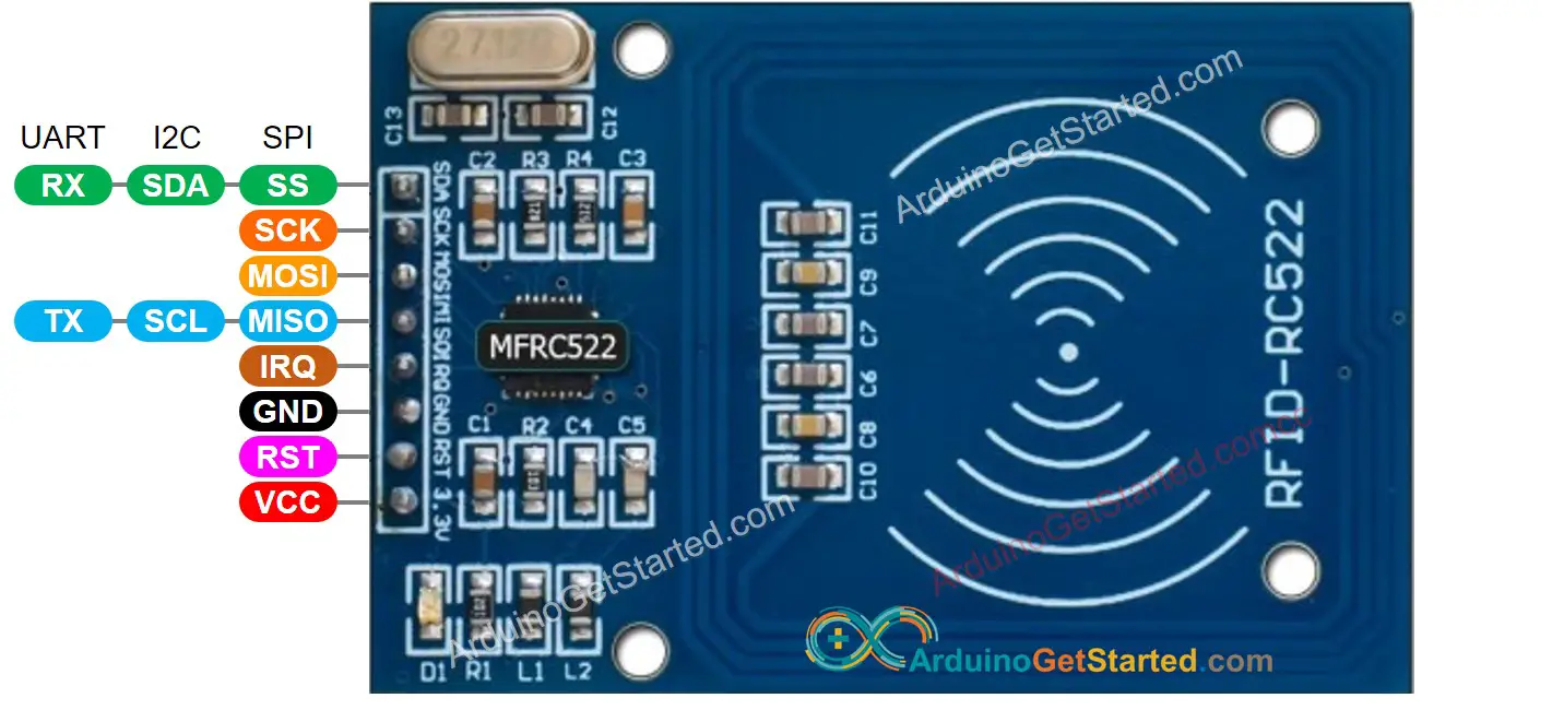
RFID-RC522 Module Pinout
RFID-RC522 has 8 pins, some of them are common pins, the others are shared among three communication modes: SPI, I2C, UART. At a time, only one communication mode can be used. The pin are:
- GND pin: needs to be connected to GND (0V)
- VCC pin: needs to be connected to VCC (3.3)
- RST pin: is a pin for reset and power-down. When this pin goes low, hard power-down is enabled. On the rising edge, the module is reset.
- IRQ pin: is an interrupt pin that can alert the microcontroller when RFID tag comes into its vicinity.
- MISO/SCL/TX pin: acts as MISO when SPI interface is enabled, acts as SCL when I2C interface is enabled and acts as TX when UART interface is enabled.
- MOSI pin: acts as MOSI when SPI interface is enabled.
- SCK pin: acts as SCK when SPI interface is enabled
- SS/SDA/RX pin: acts as SS when SPI interface is enabled, acts as SDA when I2C interface is enabled and acts as RX when UART interface is enabled.
※ NOTE THAT:
- The order of pins can vary according to manufacturers. ALWAYS use the labels printed on the module. The above image shows the pinout of the module from DIYables manufacturer.
- Do not connect VCC pin to 5V pin. This will likely destroy your module.
- MFRC522 library supports only SPI mode. Therefore, this tutorial uses only SPI communication.
How RFID/NFC Works
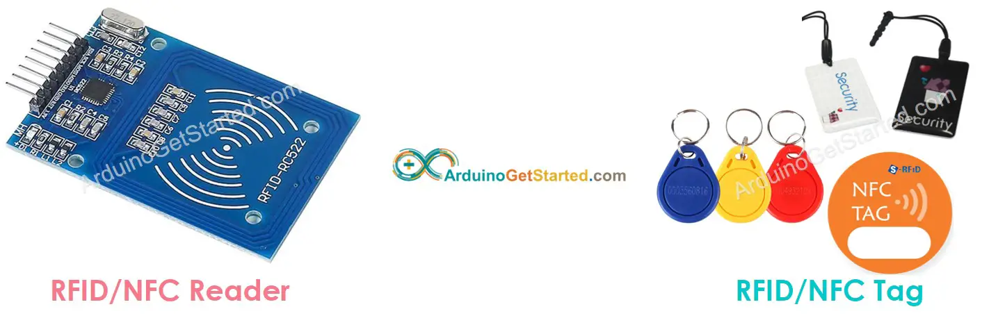
RFID/NFC includes two components: reader and tag.
- The reader consists of a radio frequency module and an antenna which generates high frequency electromagnetic field.
- The tag is usually a passive device, which doesn’t need to have power source. The tag contains a microchip that stores and processes information, and an antenna to receive and transmit a signal. The tag is used to store the information: UID (Unique ID) and data.
To read the information on a tag, the tag must be in close proximity to the reader (does not require the direct line-of-sight). The reading processes:
- The reader generates an electromagnetic field which causes electrons to move through the tag’s antenna and subsequently power the chip.
- The chip inside the tag then responds by sending the requested information back to the reader in the form of another radio signal.
- The reader detects the signal and transform the signal into data
- Arduino reads the data from reader.
Wiring Diagram between RFID-RC522 Module and Arduino
The RFID-RC522 Module is designed to operate at a 3.3V level, while the output pins of an Arduino produce a 5V level. So:
- To be safe, It needs to regulate 5V voltage from Arduino pins to 3.3V before connecting to the RC522 Module
- To be simple and for the testing purpose, it can connect Arduino pins directly to RC522 Module, but doing so might cause the Arduino to stop working correctly in some cases.
This tutorial provide two different wiring diagrams for both cases:
- Wiring Diagram between RC522 and Arduino without voltage regulator
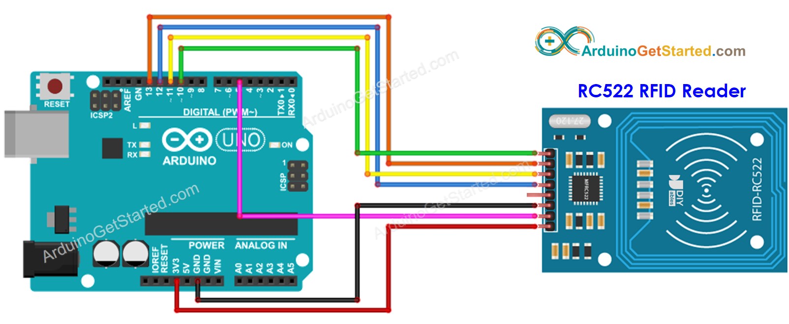
This image is created using Fritzing. Click to enlarge image
- Wiring Diagram between RC522 and Arduino with voltage regulator
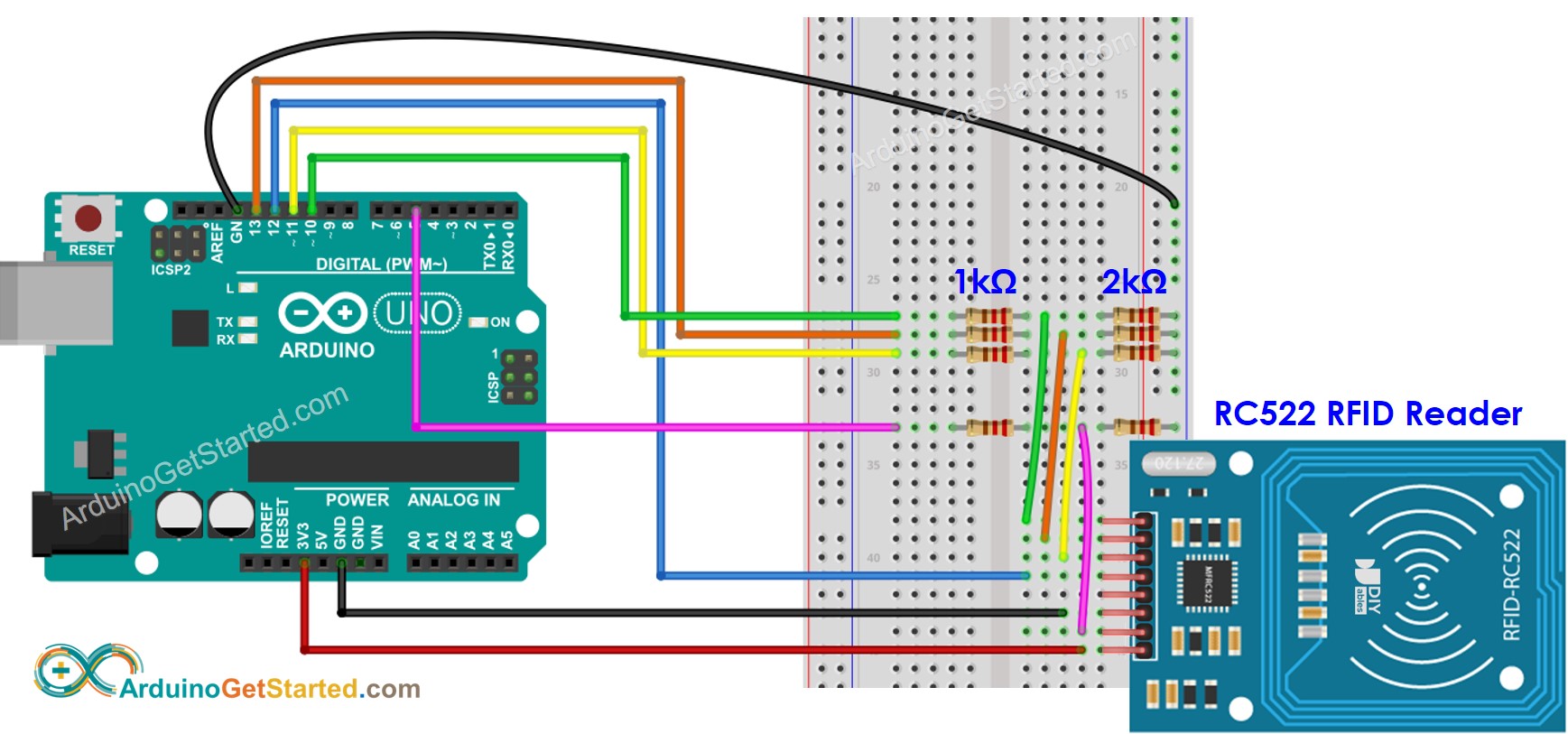
This image is created using Fritzing. Click to enlarge image
As shown in the wiring diagram above, 1kOhM and 2kOhm pair of resistors are used to regulate 5V to 3.3V. It does not need to adjust the voltage between the Arduino pin and the MISO pin of the RC522 module. However, it is necessary to regulate the voltage between the Arduino pins and the SS, SCK, MOSI, and RST pins of the RC522 module.
Wiring table of RFID/NFC RC522 Module and Arduino
| RFID/NFC RC522 | Arduino |
|---|---|
| SS | → 10 |
| SCK | → 13 |
| MOSI | → 11 |
| MISO | → 12 |
| IRQ(not connected) | |
| GND | → GND |
| RST | → 5 |
| VCC | → 3.3V |
Arduino RFID/NFC Code
Quick Steps
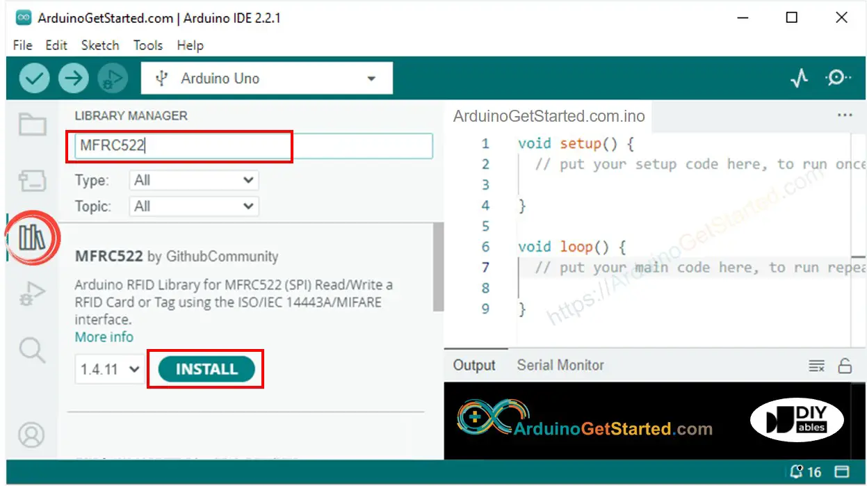
- Navigate to the Libraries icon on the left bar of the Arduino IDE.
- Search “MFRC522”, then find the library by GithubCommunity
- Click Install button to install MFRC522 library.
- Copy the above code and open with Arduino IDE
- Click Upload button on Arduino IDE to upload code to Arduino
- Open Serial Monitor
- Tap several RFID/NFC tags on RFID-RC522 module
- See UID on Serial Monitor
Video Tutorial
We are considering to make the video tutorials. If you think the video tutorials are essential, please subscribe to our YouTube channel to give us motivation for making the videos.