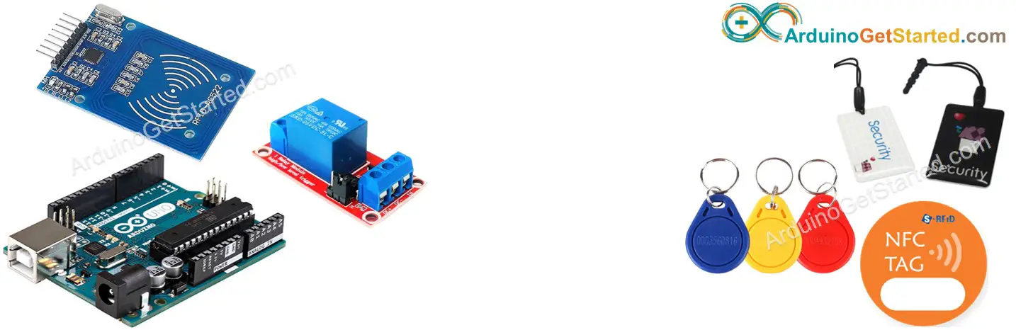
In this tutorial, we are going to learn how to use RFID/NFC tag to activate relay using Arduino. You can extend this tutorial by using the relay to control motor, actuator...
Disclosure: Some links in this section are Amazon affiliate links. If you make a purchase through these links, we may earn a commission at no extra cost to you. Additionally, some links direct to products from our own brand, DIYables .
About RFID/NFC RC522 Module and Relay
If you do not know about RFID/NFC RC522 Module and relay (pinout, how it works, how to program ...), learn about them in the following tutorials:
The UIDs of some RFID/NFC tags are preset in Arduino code
User taps an RFID/NFC tag on RFID/NFC reader
The reader reads UID from the tag.
Arduino gets the UID from the reader
Arduino compares the read UID with the predefined UIDs
If the UID is matched with one of the predefined UIDs, Arduino activates the relay.
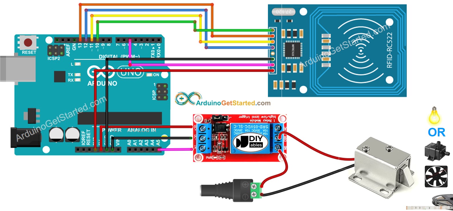
Wiring Diagram
This image is created using Fritzing. Click to enlarge image
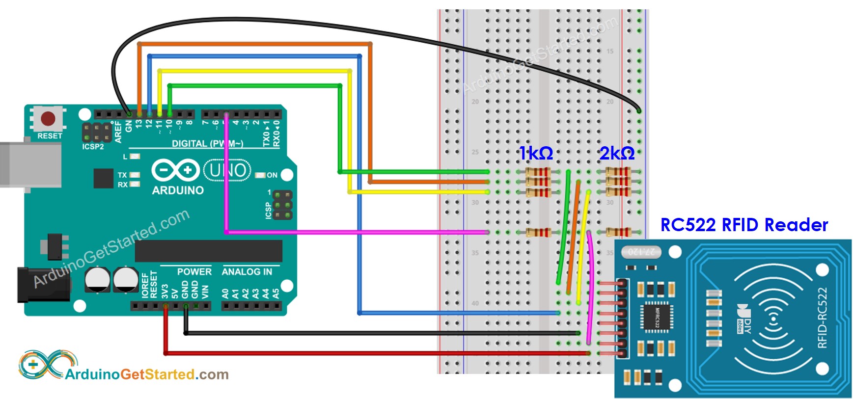
To simplify the setup, the pins of the RC522 module are directly connected to the pins of the Arduino. However, this can cause the Arduino to stop working in certain situations, as the output pins of the Arduino supply 5V while the RC522 module's pins are designed to function at 3.3V. It is therefore advisable to regulate the voltage between the Arduino pins and the RC522 module's pins. For additional information, please refer to the Arduino - RFID RC522 tutorial. The following diagram illustrates how to use resistors to regulate 5V to 3.3V:
This image is created using Fritzing. Click to enlarge image
※ NOTE THAT:
The order of pins can vary according to manufacturers. ALWAYS use the labels printed on the module. The above image shows the pinout of the modules from DIYables manufacturer.
Arduino Code - Single RFID/NFC Tag
/* * Created by ArduinoGetStarted.com * * This example code is in the public domain * * Tutorial page: https://arduinogetstarted.com/tutorials/arduino-rfid-nfc-relay */#include <SPI.h>#include <MFRC522.h>#define SS_PIN 10#define RST_PIN 5#define RELAY_PIN A5 // the Arduino pin connects to relayMFRC522 rfid(SS_PIN, RST_PIN);byte authorizedUID[4] = {0xFF, 0xFF, 0xFF, 0xFF};voidsetup() {Serial.begin(9600);SPI.begin(); // init SPI bus rfid.PCD_Init(); // init MFRC522pinMode(RELAY_PIN, OUTPUT); // initialize pin as an output.digitalWrite(RELAY_PIN, LOW); // deactivate the relaySerial.println("Tap RFID/NFC Tag on reader");}voidloop() {if (rfid.PICC_IsNewCardPresent()) { // new tag is availableif (rfid.PICC_ReadCardSerial()) { // NUID has been readedMFRC522::PICC_Type piccType = rfid.PICC_GetType(rfid.uid.sak);if (rfid.uid.uidByte[0] == authorizedUID[0] && rfid.uid.uidByte[1] == authorizedUID[1] && rfid.uid.uidByte[2] == authorizedUID[2] && rfid.uid.uidByte[3] == authorizedUID[3] ) {Serial.println("Authorized Tag");digitalWrite(RELAY_PIN, HIGH); // activate the relay for 2 secondsdelay(2000);digitalWrite(RELAY_PIN, LOW); // deactivate the relay }else {Serial.print("Unauthorized Tag with UID:");for (int i = 0; i < rfid.uid.size; i++) {Serial.print(rfid.uid.uidByte[i] < 0x10 ? " 0" : " ");Serial.print(rfid.uid.uidByte[i], HEX); }Serial.println(); } rfid.PICC_HaltA(); // halt PICC rfid.PCD_StopCrypto1(); // stop encryption on PCD } }}
Quick Steps
Because UID is usually not printed on RFID/NFC tag, The first step we need to do is to find out the tag's UID. This can be done by:
Copy the above code and open with Arduino IDE
Click Upload button on Arduino IDE to upload code to Arduino
Open Serial Monitor
Tap an RFID/NFC tag on RFID-RC522 module
Get UID on Serial Monitor
Newbiely | Arduino IDE 2.3.8
──
☐
✕
File
Edit
Sketch
Tools
Help
Arduino Uno
Newbiely.ino
···
8Serial.println("Hello World!");
Output
Serial Monitor
Message (Enter to send message to 'Arduino Uno' on 'COM15')
New Line
9600 baud
Tap RFID/NFC tag on reader
Unauthorized Tag with UID: 3A C9 6A CB
Ln 11, Col 1
Arduino Uno on COM15
2
After having UID:
Update UID in the line 18 of the above code. For example, change byte authorizedUID[4] = {0xFF, 0xFF, 0xFF, 0xFF}; TO byte authorizedUID[4] = {0x3A, 0xC9, 0x6A, 0xCB};
Upload the code to Arduino again
Tap an RFID/NFC tag on RFID-RC522 module
See output on Serial Monitor
Newbiely | Arduino IDE 2.3.8
──
☐
✕
File
Edit
Sketch
Tools
Help
Arduino Uno
Newbiely.ino
···
8Serial.println("Hello World!");
Output
Serial Monitor
Message (Enter to send message to 'Arduino Uno' on 'COM15')
New Line
9600 baud
Tap RFID/NFC tag on reader
Authorized Tag
Ln 11, Col 1
Arduino Uno on COM15
2
Tap another RFID/NFC tag on RFID-RC522 module
See output on Serial Monitor
Newbiely | Arduino IDE 2.3.8
──
☐
✕
File
Edit
Sketch
Tools
Help
Arduino Uno
Newbiely.ino
···
8Serial.println("Hello World!");
Output
Serial Monitor
Message (Enter to send message to 'Arduino Uno' on 'COM15')
New Line
9600 baud
Tap RFID/NFC tag on reader
Authorized Tag
Unauthorized Tag with UID: BD 1E 1D 00
Ln 11, Col 1
Arduino Uno on COM15
2
※ NOTE THAT:
To make it easy to test, The active time is 2 seconds, it should be increased in practical use/demonstration
We can allow multiple RFID/NFC tags to activate the relay. The below code uses two tags as an example.
/* * Created by ArduinoGetStarted.com * * This example code is in the public domain * * Tutorial page: https://arduinogetstarted.com/tutorials/arduino-rfid-nfc-relay */#include <SPI.h>#include <MFRC522.h>#define SS_PIN 10#define RST_PIN 5#define RELAY_PIN A5 // the Arduino pin connects to relayMFRC522 rfid(SS_PIN, RST_PIN);byte authorizedUID1[4] = {0x3A, 0xC9, 0x6A, 0xCB};byte authorizedUID2[4] = {0x30, 0x01, 0x8B, 0x15}; voidsetup() {Serial.begin(9600);SPI.begin(); // init SPI bus rfid.PCD_Init(); // init MFRC522pinMode(RELAY_PIN, OUTPUT); // initialize pin as an output.digitalWrite(RELAY_PIN, LOW); // deactivate the relaySerial.println("Tap RFID/NFC Tag on reader");}voidloop() {if (rfid.PICC_IsNewCardPresent()) { // new tag is availableif (rfid.PICC_ReadCardSerial()) { // NUID has been readedMFRC522::PICC_Type piccType = rfid.PICC_GetType(rfid.uid.sak);if (rfid.uid.uidByte[0] == authorizedUID1[0] && rfid.uid.uidByte[1] == authorizedUID1[1] && rfid.uid.uidByte[2] == authorizedUID1[2] && rfid.uid.uidByte[3] == authorizedUID1[3] ) {Serial.println("Authorized Tag 1");digitalWrite(RELAY_PIN, HIGH); // activate the relay for 2 secondsdelay(2000);digitalWrite(RELAY_PIN, LOW); // deactivate the relay }elseif (rfid.uid.uidByte[0] == authorizedUID2[0] && rfid.uid.uidByte[1] == authorizedUID2[1] && rfid.uid.uidByte[2] == authorizedUID2[2] && rfid.uid.uidByte[3] == authorizedUID2[3] ) {Serial.println("Authorized Tag 2");digitalWrite(RELAY_PIN, HIGH); // activate the relay for 2 secondsdelay(2000);digitalWrite(RELAY_PIN, LOW); // deactivate the relay }else {Serial.print("Unauthorized Tag with UID:");for (int i = 0; i < rfid.uid.size; i++) {Serial.print(rfid.uid.uidByte[i] < 0x10 ? " 0" : " ");Serial.print(rfid.uid.uidByte[i], HEX); }Serial.println(); } rfid.PICC_HaltA(); // halt PICC rfid.PCD_StopCrypto1(); // stop encryption on PCD } }}
Do the similar steps as the above, and then tap one by one tag on RFID-RC522 module. The result on Serial Monitor looks like below:
Newbiely | Arduino IDE 2.3.8
──
☐
✕
File
Edit
Sketch
Tools
Help
Arduino Uno
Newbiely.ino
···
8Serial.println("Hello World!");
Output
Serial Monitor
Message (Enter to send message to 'Arduino Uno' on 'COM15')
New Line
9600 baud
Tap RFID/NFC tag on reader
Authorized Tag 2
Authorized Tag 1
Ln 11, Col 1
Arduino Uno on COM15
2
You can extend the above code for three, four, or more tags.
Video Tutorial
We are considering to make the video tutorials. If you think the video tutorials are essential, please subscribe to our YouTube channel to give us motivation for making the videos.
You can share the link of this tutorial anywhere. Howerver, please do not copy the content to share on other websites. We took a lot of time and effort to create the content of this tutorial, please respect our work!