Arduino - Motion Sensor - Relay
We are going to learn how to:
- If the motion is detected, turn relay on
- If the motion is not detected, turn relay off
By connecting relay to light bulb, led strip, motor or actuator... We can use the motion sensor to control light bulb, led strip, motor or actuator...
Hardware Required
Or you can buy the following kits:
| 1 | × | DIYables STEM V3 Starter Kit (Arduino included) | |
| 1 | × | DIYables Sensor Kit (18 sensors/displays) |
Disclosure: Some links in this section are Amazon affiliate links. If you make a purchase through these links, we may earn a commission at no extra cost to you.
Additionally, some links direct to products from our own brand, DIYables .
Additionally, some links direct to products from our own brand, DIYables .
About Relay and Motion Sensor
If you do not know about relay and motion sensor (pinout, how it works, how to program ...), learn about them in the following tutorials:
Wiring Diagram
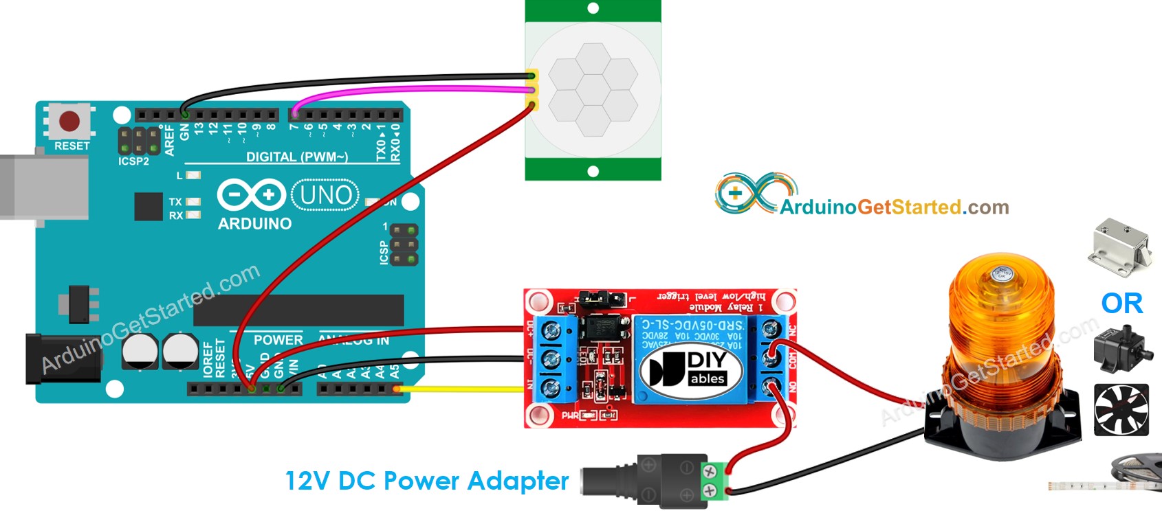
This image is created using Fritzing. Click to enlarge image
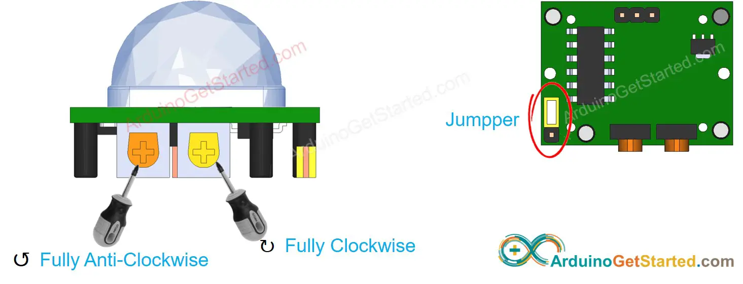
Initial Setting
| Time Delay Adjuster | Screw it in anti-clockwise direction fully. |
| Detection Range Adjuster | Screw it in clockwise direction fully. |
| Repeat Trigger Selector | Put jumper as shown on the image. |
Arduino Code
/*
* Created by ArduinoGetStarted.com
*
* This example code is in the public domain
*
* Tutorial page: https://arduinogetstarted.com/tutorials/arduino-motion-sensor-relay
*/
const int MOTION_SENSOR_PIN = 7; // Arduino pin connected to the OUTPUT pin of motion sensor
const int RELAY_PIN = A5; // Arduino pin connected to the IN pin of relay
int motionStateCurrent = LOW; // current state of motion sensor's pin
int motionStatePrevious = LOW; // previous state of motion sensor's pin
void setup() {
Serial.begin(9600); // initialize serial
pinMode(MOTION_SENSOR_PIN, INPUT); // set arduino pin to input mode
pinMode(RELAY_PIN, OUTPUT); // set arduino pin to output mode
}
void loop() {
motionStatePrevious = motionStateCurrent; // store old state
motionStateCurrent = digitalRead(MOTION_SENSOR_PIN); // read new state
if (motionStatePrevious == LOW && motionStateCurrent == HIGH) { // pin state change: LOW -> HIGH
Serial.println("Motion detected!");
digitalWrite(RELAY_PIN, HIGH); // turn on
}
else
if (motionStatePrevious == HIGH && motionStateCurrent == LOW) { // pin state change: HIGH -> LOW
Serial.println("Motion stopped!");
digitalWrite(RELAY_PIN, LOW); // turn off
}
}
Quick Steps
- Connect Arduino to PC via USB cable
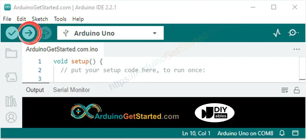
- Open Arduino IDE, select the right board and port
- Copy the above code and open with Arduino IDE
- Click Upload button on Arduino IDE to upload code to Arduino
- Move your hand in front of sensor
- See the change of relay's state
Code Explanation
Read the line-by-line explanation in comment lines of source code!
Video Tutorial
We are considering to make the video tutorials. If you think the video tutorials are essential, please subscribe to our YouTube channel to give us motivation for making the videos.