Arduino - Door Lock System using Password
In this tutorial, we learn how to make door lock system with password. The tutorial include two main parts:
- Arduino - Door lock system with password using keypad, electromagnetic lock.
- Arduino - Door lock system with password using keypad, electromagnetic lock and LCD.
LCD is optional. It just makes the system a little more convenient.
When the door is unlocked by a correct password, It keeps the door unlocked for 20 seconds, and then automatically lock the door again. The Arduino code supports multiple passwords.
※ NOTE THAT:
We also have others door lock system tutorials:
Hardware Required
Or you can buy the following kits:
| 1 | × | DIYables STEM V3 Starter Kit (Arduino included) | |
| 1 | × | DIYables Sensor Kit (18 sensors/displays) |
Additionally, some links direct to products from our own brand, DIYables .
Buy Note: Another option is to create the LCD I2C display by pairing LCD 1602 Display and PCF8574 I2C Adapter Module.
About Keypad and Electromagnetic Lock and LCD
If you do not know about electromagnetic lock Keypad and LCD (pinout, how it works, how to program ...), learn about them in the following tutorials:
How door lock system works
Valid passwords are pre-defined in the Arduino code.
A string is used to store the input password from users, called input string. In keypad, two keys (* and #) are used for special purposes: clear password and terminate password. The system works as follows:
- Except for two special keys, if another key is pressed, it is appended to the input string
- If * is pressed, input string is clear. You can use it to start or re-start inputing the password
- If # is pressed:
- The input string is compared with the pre-defined passwords. If it matched with one of the pre-defined passwords, the door is unlocked.
- No matter the password is correct or not, the input string is clear for the next input
Wiring Diagram
- Arduino - Door lock system with password using keypad, electromagnetic lock
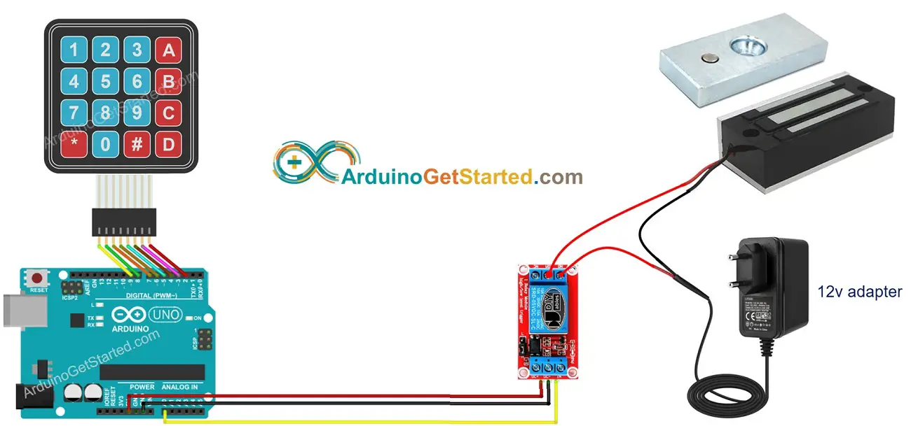
This image is created using Fritzing. Click to enlarge image
- Arduino - Door lock system with password using keypad, electromagnetic lock and LCD
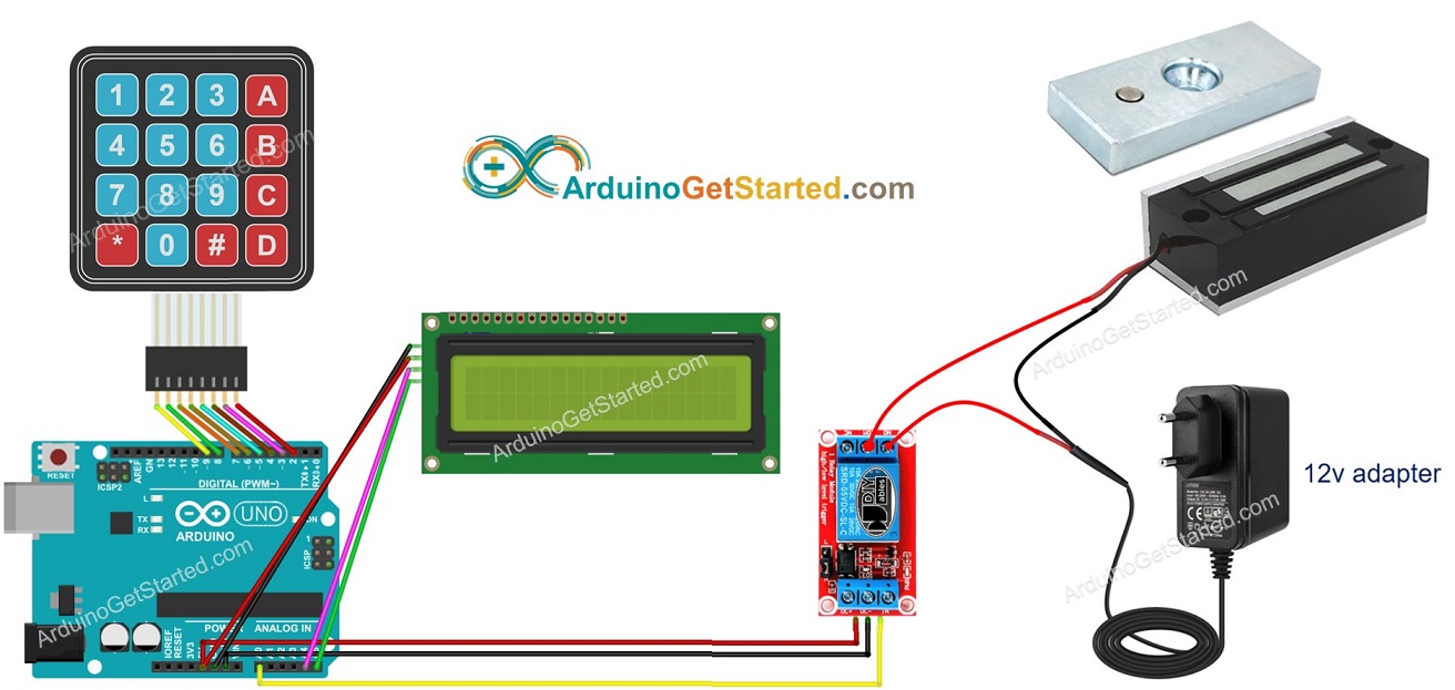
This image is created using Fritzing. Click to enlarge image
Arduino Code - Door lock system with password using keypad, electromagnetic lock
Quick Steps
- Connect Arduino to PC via USB cable
- Open Arduino IDE, select the right board and port
- Navigate to the Libraries icon on the left bar of the Arduino IDE.
- Search “keypad”, then find the keypad library by Mark Stanley, Alexander Brevig
- Click Install button to install keypad library.
- Copy the above code and open with Arduino IDE
- Click Upload button on Arduino IDE to upload code to Arduino
- Put the armature plate close to electromagnet.
- Open Serial Monitor
- Press 123456 keys and press #
- Press 1234ABC keys and press #
- See the attraction between armature plate and electromagnet during 20 seconds.
- See the result on Serial Monitor
Arduino Code - Door lock system with password using keypad, electromagnetic lock and LCD
※ NOTE THAT:
The I2C address of LCD can vary according to the manufacturers. In the code, we used 0x27 that is specified by DIYables manufacturer
Quick Steps
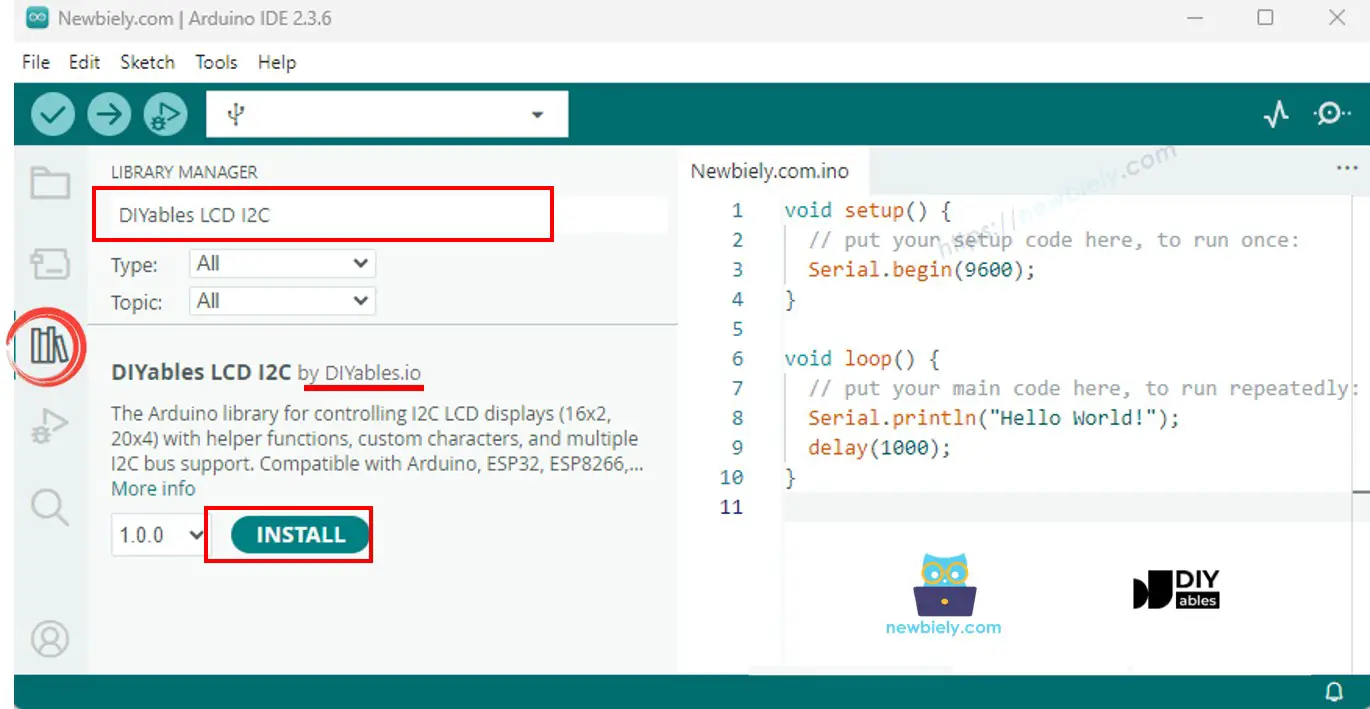
- Navigate to the Libraries icon on the left bar of the Arduino IDE.
- Search “DIYables LCD I2C”, then find the DIYables_LCD_I2C library by DIYables
- Click Install button to install DIYables_LCD_I2C library.
- Copy the above code and open with Arduino IDE
- Click Upload button on Arduino IDE to upload code to Arduino
- Put the armature plate close to electromagnet.
- Input a wrong password, and then input a correct password
- See the attraction between armature plate and electromagnet during 20 seconds.
- See text on LCD
※ NOTE THAT:
- In the above codes, To make it simple, we used the delay function. It is better to use millis() instead of delay(). See How to use millis() instead of delay()
- You can add a piezo buzzer to make the beep sound each time keypad is pressed.
- In the above codes, the door is locked again after 20 seconds. You can replace it by a door sensor. The door is locked when the door sensor detect the door is closed by user.
- In the above code, the passwords are hard-coded. In the practice, it should be able to add/delete/change passwords dynamically via a special mode. If so, the passwords should be saved on EEPROM memory. The number of passwords can be saved depends on the EEPROM's size. The code will become complicated. If you want to build such system, we provide a coding service. Please feel free to contact us.
Video Tutorial
We are considering to make the video tutorials. If you think the video tutorials are essential, please subscribe to our YouTube channel to give us motivation for making the videos.