Arduino - Control Stepper Motor using L298N Driver
In this tutorial, we are going to learn:
- How to use L298N driver to control bipolar stepper motor
- How to control the position of stepper motor
- How to control the speed of stepper motor
- How to control the direction of stepper motor
The tutorial can apply to any kind of bipolar stepper motor (4 wires). The tutorial will take NEMA 17 stepper motor as an example.
Hardware Required
Or you can buy the following kits:
| 1 | × | DIYables STEM V3 Starter Kit (Arduino included) | |
| 1 | × | DIYables Sensor Kit (18 sensors/displays) |
Additionally, some links direct to products from our own brand, DIYables .
About Stepper Motor
There are two popular types of stepper motors:
- bipolar: this type of motor has 4 wires
- unipolar: this type of motor has 5 wires or 6 wires.
For a 6-wire unipolar stepper motor, we can use four of six wires and control it as a bipolar stepper motor.
For 5-wire unipolar stepper motor, see Arduino - control 28BYJ-48 stepper motor using ULN2003 driver
This tutorial focuses only on the bipolar stepper motor.
Bipolar Stepper Motor pinout
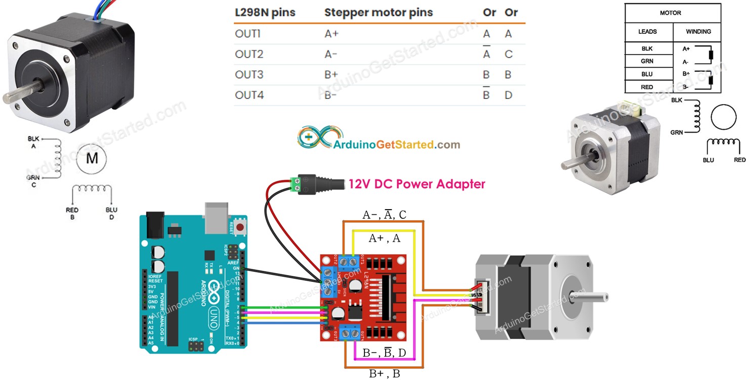
The bipolar Stepper Motor pinout has 4 pins. Depending on manufacturers, the motor's pins have several naming. The below table shows some wide-used pin-naming:
| PIN NO | Naming 1 | Naming 2 | Naming 3 |
|---|---|---|---|
| 1 | A+ | A | A |
| 2 | A- | A | C |
| 3 | B+ | B | B |
| 4 | B- | B | D |
The order of pins, wire naming, and wire coloring can vary between manufacturers. You need to read the datasheet or manual to see the mapping between wire color and pin name. The above image also shows the specification of two different motors with different wire naming and wire coloring.
Steps per Revolution
The motor's specification specifies the degree per step (let's call DEG_PER_STEP). Depending on the method of control, the steps per revolution (let's call STEP_PER_REVOLUTION) is calculated as the following table:
| Control method | Steps per Revolution | Real degree per step |
|---|---|---|
| Full-step | STEP_PER_REVOLUTION = 360 / DEG_PER_STEP | DEG_PER_STEP |
| Half-step | STEP_PER_REVOLUTION = (360 / DEG_PER_STEP) * 2 | DEG_PER_STEP / 2 |
| Micro-step (1/n) | STEP_PER_REVOLUTION = (360 / DEG_PER_STEP) * n | DEG_PER_STEP / n |
For example, If the motor's datasheet specifies 1.8 degree/step:
| Control method | Steps per Revolution | Real degree per step |
|---|---|---|
| Full-step | 200 steps/revolution | 1.8° |
| Half-step | 400 steps/revolution | 0.9° |
| Micro-step (1/n) | (200 * n) steps/revolution | (1.8 / n)° |
How to control a stepper motor using Arduino
Arduino can generate signals to control the stepper motor. However, the signals from Arduino do not have enough voltage and/or current that the stepper motor requires. Therefore, we need a hardware driver in between Arduino and the stepper motor. The driver does two works:
- Amplify the control signals from Arduino (current and voltage)
- Protect Arduino from high current and voltage that is used to power the stepper motor.
There are many kinds of hardware drivers that can be used to control stepper motors. L298N Driver is one of the most wide-used hardware drivers for controlling stepper motors.
About L298N Driver
A single L298N Driver can be used to control two DC motors or a stepper motor. In this tutorial, we learn how to use it to control the stepper motor.

L298N Driver Pinout
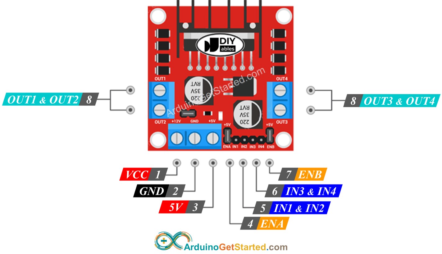
L298N Driver has 11 pins and three jumpers:
- VCC pin: supplies power for the motor. It can be anywhere between 5 to 35V.
- GND pin: is a common ground pin, needs to be connected to GND (0V).
- 5V pin: supplies power for L298N module. It can be supplied by 5V from Arduino.
- IN1, IN2, IN3, IN4 pins: are connected to Arduino's pins to receive the control signal to control the stepper motor.
- OUT1, OUT2, OUT3, OUT4 pins: are connected to the stepper motor.
- ENA, ENB jumpers: are used to enable stepper motor. You need to keep both the ENA & ENB jumpers in place.
- 5V-EN jumper: if we keep 5V-EN jumper in place, the power for the L298N module is got from VCC, we do not need to connect anything to the 5V pin. if we remove the 5V-EN jumper, we need to supply power to the L298N module via a 5V pin
As described above, the L298N driver has two input powers:
- One for stepper motor (VCC and GND pins): from 5 to 35V.
- One for the L298N module's internal operation (5V and GND pins): from 5 to 7V. if the 5V-EN jumper is kept in place, we do not need to connect this pin to anything.
Wiring Diagram
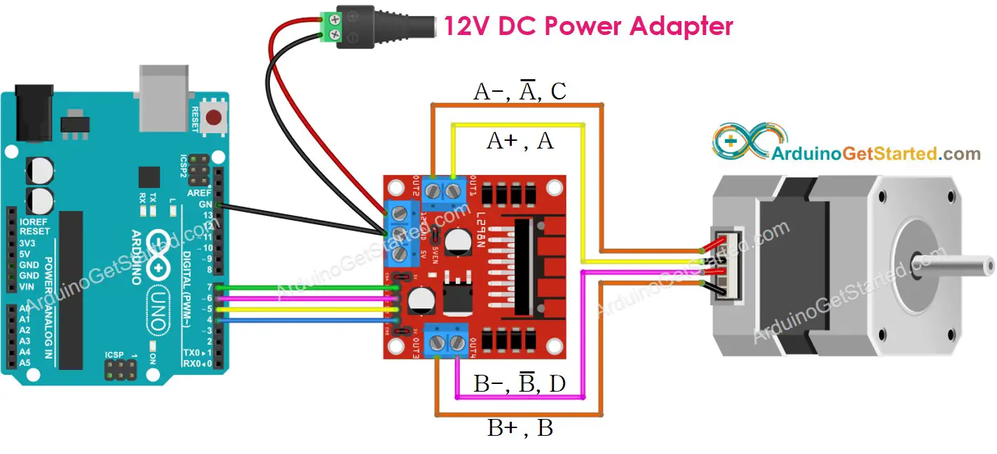
This image is created using Fritzing. Click to enlarge image
※ NOTE THAT:
- Please keep all three jumpers on the L298N module in place (in case motor's power supply ≤ 12V)
- Order of the pins on stepper motors may vary between manufacturers. Please check the below table for correct wiring.
Wiring table between Arduino and L298N Driver
| Arduino pins | L298N pins |
|---|---|
| 7 | IN1 |
| 6 | IN2 |
| 5 | IN3 |
| 4 | IN4 |
Wiring table between L298N Driver and Stepper motor
Important!: Please do not care about the wire order of the stepper motor on the above wiring diagram image. It is just an example. The order of the pins on stepper motors may vary between manufacturers. Make sure that your wiring follows the below table.
| L298N pins | Stepper motor pins | Or | Or |
|---|---|---|---|
| OUT1 | A+ | A | A |
| OUT2 | A- | A | C |
| OUT3 | B+ | B | B |
| OUT4 | B- | B | D |
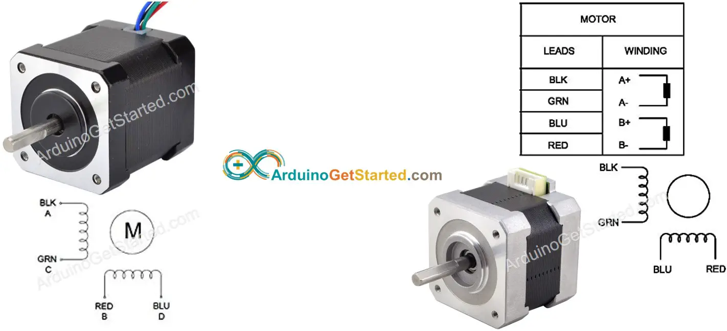
Before buying a stepper motor, we would recommend you check the check datasheet, specification, or manual of the stepper motor. Make sure that they provide the mapping between the pin's color and name. For example, This stepper motor provides the mapping as below image:
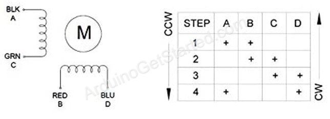
Based on that mapping, the wiring table becomes:
| L298N pins | stepper motor pins | wire color |
|---|---|---|
| OUT1 | A | black wire |
| OUT2 | C | green wire |
| OUT3 | B | red wire |
| OUT4 | D | blue wire |
※ NOTE THAT:
In all the above wiring tables between the stepper motor and L298N Driver, we can swap OUT1 with OUT2, OUT3 with OUT4. Therefore, there are more ways to do the wiring. However, if we swap them, the motors' rotation direction may be changed (clockwise to anticlockwise, and vice versa).
How to control a Stepper motor using an L298N driver.
Controlling a stepper motor is not a simple task, especially when we want to control it in a non-blocking manner. Fortunately, thanks to AccelStepper library, controlling the stepper motor becomes a piece of cake.
Arduino IDE also has a built-in Stepper library. However, We do not recommend you to use this library because:
- The library provides the blocking function. It means it blocks Arduino from doing other works while it controls the stepper motor.
- It does not have sufficient functions.
Instead, we recommend you use the AccelStepper library. This library supports:
- Acceleration
- Deceleration.
- Full-step and half-step driving.
- Multiple simultaneous steppers, with independent concurrent stepping on each stepper.
- Disadvantage: NOT support micro-step driving
How To Control the Position of Stepper Motor via L298N Driver
We can move the stepper motor to the desired position by using:
※ NOTE THAT:
The stepper.moveTo() function is non-blocking. This is a great point of the library. However, we have to pay attentions when using this function:
- Call 'stepper.run()' as frequently as possible. It should be called in the void loop() function.
- Do NOT use delay() function when motor is moving.
- Should NOT use Serial.print() and Serial.println() function when motor is moving. These functions make the stepper motor move slower.
How To Control the Speed of Stepper Motor via L298N Driver
We can control not only the speed but also acceleration and deceleration by using some simple functions.
How To Control the Direction of Stepper Motor via L298N Driver
If you do the wiring as above, the motor will rotate in:
- Clockwise direction: if we control the motor from a position to higher position (Position increment)
- Anticlockwise direction: if we control the motor from a position to lower position (Position decrement)
For example:
- If the current position is 100 and we control the motor to 200, the motor rotates in the clockwise direction
- If the current position is -200 and we control the motor to -100, the motor rotates in the clockwise direction
- If the current position is 200 and we control the motor to 100, the motor rotates in the anticlockwise direction
- If the current position is -100 and we control the motor to -200, the motor rotates in the anticlockwise direction
※ NOTE THAT:
As mentioned before, if you swap OUT1 with OUT2, or OUT3 with OUT4, the increment of the position may be anticlockwise and the decrement of the position may be clockwise.
How To Stop Stepper Motor
- The stepper motor will automatically stop after reaching the desired position.
- The stepper motor can be forced to stop immediately anytime by using stepper.stop() function.
Arduino Code - Stepper Motor Code
The below code does:
- Rotate motor one revolution in the clockwise direction
- Stop motor 5 seconds
- Rotate motor back one revolution in the anticlockwise direction
- Stop motor 5 seconds
- That process is repeated again and again
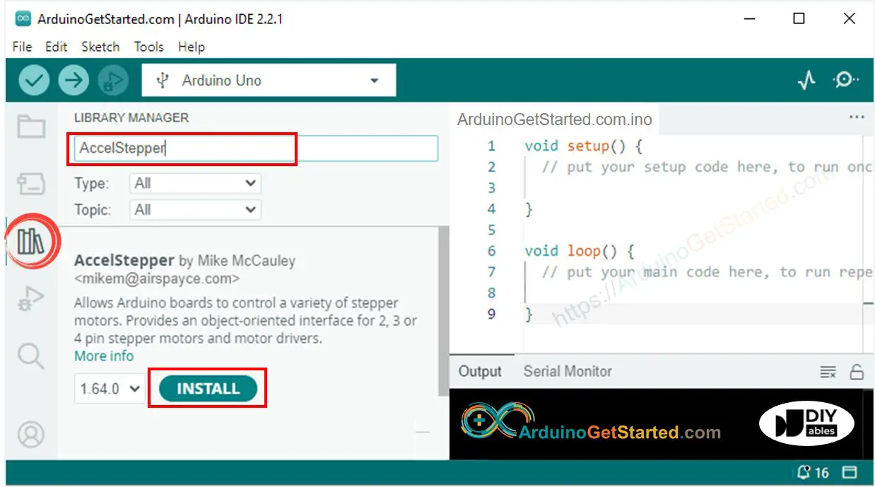
Quick Steps
- Navigate to the Libraries icon on the left bar of the Arduino IDE.
- Search “AccelStepper”, then find the AccelStepper library by Mike McCauley
- Click Install button to install AccelStepper library.
- Copy the above code and open with Arduino IDE
- Click Upload button on Arduino IDE to upload code to Arduino
- You will see:
- Stepper motor rotates one revolution in the clockwise direction
- Stepper motor stops 5 seconds
- Stepper motor rotates back one revolution in the anticlockwise direction
- Stepper motor stops 5 seconds
- The above process is run repeatedly.
- See the result on Serial Monitor
Code Explanation
Read the line-by-line explanation in comment lines of source code!
Video Tutorial
We are considering to make the video tutorials. If you think the video tutorials are essential, please subscribe to our YouTube channel to give us motivation for making the videos.