Arduino - Control 28BYJ-48 Stepper Motor using ULN2003 Driver
In this tutorial, we are going to learn:
- How to control a single 28BYJ-48 stepper motor using Arduino and ULN2003 driver
- How to control a multiple 28BYJ-48 stepper motors using Arduino and ULN2003 driver
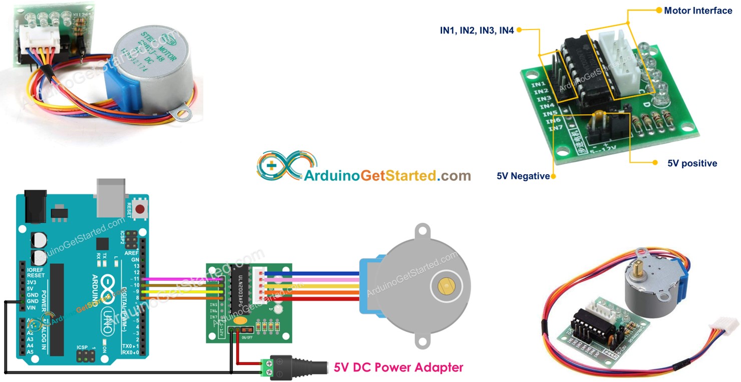
Stepper motors are great motors for position control. The stepper motors divide a full revolution into a number of equal “steps”. They are used in many devices such as printer, 3D printer, CNC machines, and used industrial automation.
One of the inexpensive way to learn about stepper motors is to use 28BYJ-48 stepper motors. They usually come with a ULN2003 based driver board which makes them super easy to use.
Hardware Required
Or you can buy the following kits:
| 1 | × | DIYables STEM V3 Starter Kit (Arduino included) | |
| 1 | × | DIYables Sensor Kit (30 sensors/displays) | |
| 1 | × | DIYables Sensor Kit (18 sensors/displays) |
Additionally, some links direct to products from our own brand, DIYables .
About 28BYJ-48 Stepper Motor
According to the data sheet, when the 28BYJ-48 motor runs in full-step mode, each step corresponds to a rotation of 11.25°. That means there are 32 steps per revolution (360°/11.25° = 32).
In addition, the motor has a 1/64 reduction gear set. It means it that it actually has 32 x 64 = 2048 steps. Each step is equivalent to 360°/2048 = 0.1758°.
Conclusion: if motor do 2048 steps (in full-step mode), the motor rotate one revolution
Pinout
28BYJ-48 stepper motor includes 5 pins. We do not need to care detail about these pins. We just need to plug it to the connector of ULN2003 motor driver.
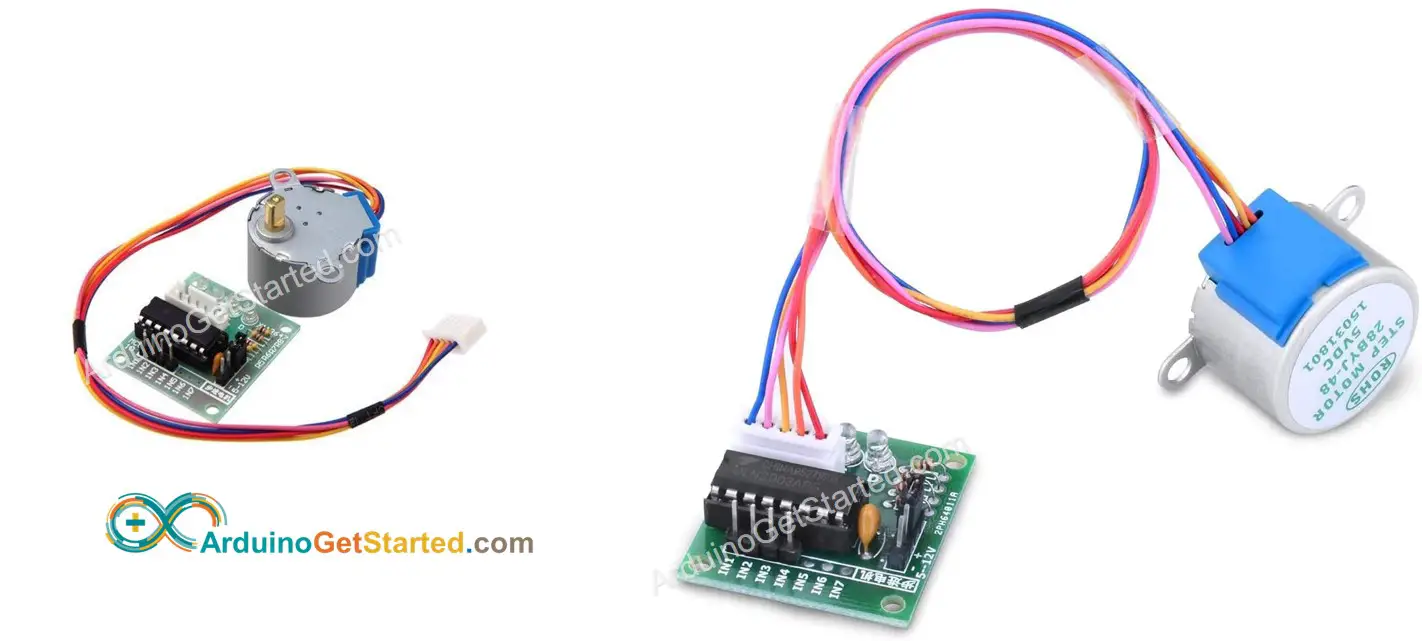
About ULN2003 Stepper Motor Driver Module
The ULN2003 is one of the most common motor driver Module for stepper motor.
- The module has four LEDs that show activity of four control input lines (to indicate stepping state). They provide a splendid effect when stepping.
- The module also comes with an ON/OFF jumper to isolate power to the stepper motor.
ULN2003 Pinout
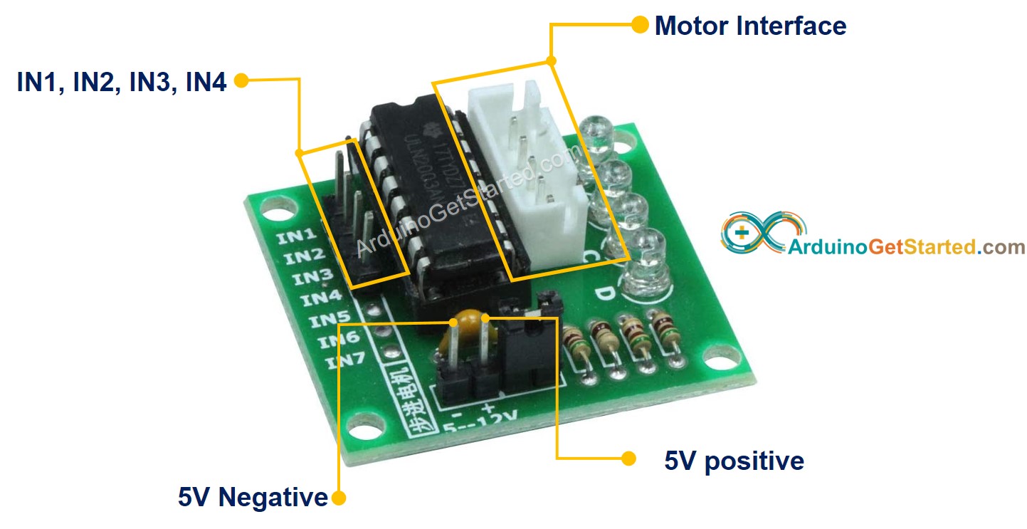
ULN2003 module includes 6 pins and one female connector:
- IN1 pin: is used to drive the motor. Connect it to an output pin on Arduino.
- IN2 pin: is used to drive the motor. Connect it to an output pin on Arduino.
- IN3 pin: is used to drive the motor. Connect it to an output pin on Arduino.
- IN4 pin: is used to drive the motor. Connect it to an output pin on Arduino.
- GND pin: is a common ground pin. It MUST connect to both GNDs of Arduino and the external power supply.
- VDD pin: supplies power for the motor. Connect it to the external power supply.
- Motor Connector: this is where the motor plugs into.
※ NOTE THAT:
- The voltage of the external power supply should be equal to the voltage of stepper motor. For example, if a stepper motor works with 12V DC, we need to use a 12V power supply. In case of 28BYJ-48 stepper motor, it works with 5V DC, we will use 5V power supply.
- Even if a stepper motor requires 5V power supply, Please do NOT connect VDD pin to the 5V pin on Arduino. Instead, connect it to an external 5V power supply. That is because the stepper motor draws too much power.
Wiring Diagram
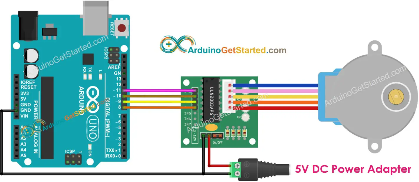
This image is created using Fritzing. Click to enlarge image
Please note that, we do not need to care about wire color of stepper motor. We just need to plug male connector ( in 28BYJ-48 stepper motor) to female connector (on ULN2003 driver)
How To Program to control a stepper motor
There are three methods to control a stepper motor:
- Full-step
- Half-step
- Micro-step
For simple application, we can use full-step method. The detail of three method will be present in the last part of this tutorial. Programming for these methods is complicated. Fortunately, there are many libraries did it for us. We just need to use library.
Arduino IDE has a built-in Stepper library. However, We do not recommend you to use this library because:
- The library is blocking. It means it blocks Arduino from doing other works while it controlling the stepper motor.
- It does not have sufficient functions.
Instead, we recommend you using the AccelStepper library. This library supports:
- Acceleration
- Deceleration.
- Full-step and half-step driving.
- Multiple simultaneous steppers, with independent concurrent stepping on each stepper.
- Disadvantage: NOT support micro-step driving
Arduino Code
Quick Steps
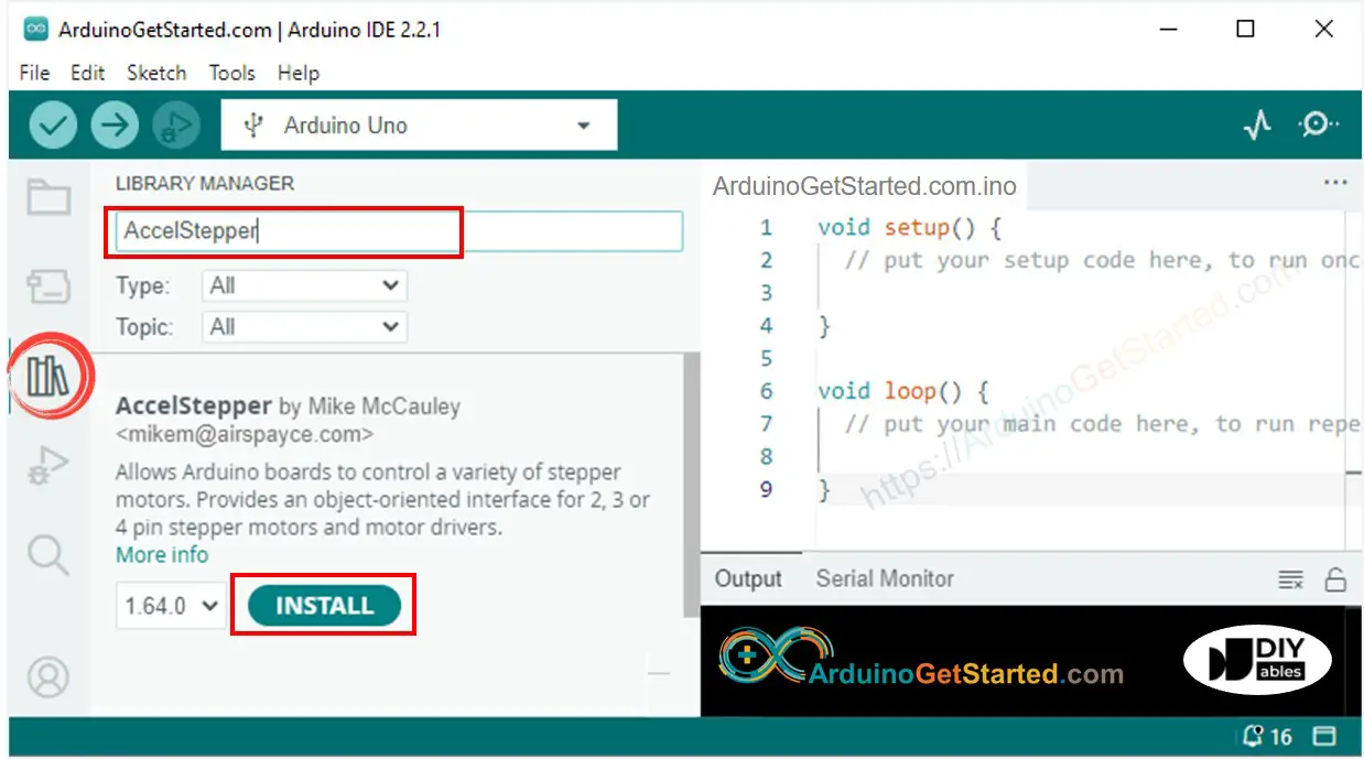
- Navigate to the Libraries icon on the left bar of the Arduino IDE.
- Search “AccelStepper”, then find the AccelStepper library by Mike McCauley
- Click Install button to install AccelStepper library.
- Copy the above code and open with Arduino IDE
- Click Upload button on Arduino IDE to upload code to Arduino
- See motor rotating. It should:
- Rotate one revolution in clockwire direction, and then
- Rotate two revolution in anti-clockwire direction, and then
- Rotate two revolution in clockwire direction.
- See the result in Serial Monitor
That preccess is repeated infinitely.
How to control a multiple 28BYJ-48 stepper motors
Let's learn how to control two stepper motor independently at the same time.
Wiring Diagram for two 28BYJ-48 stepper motors
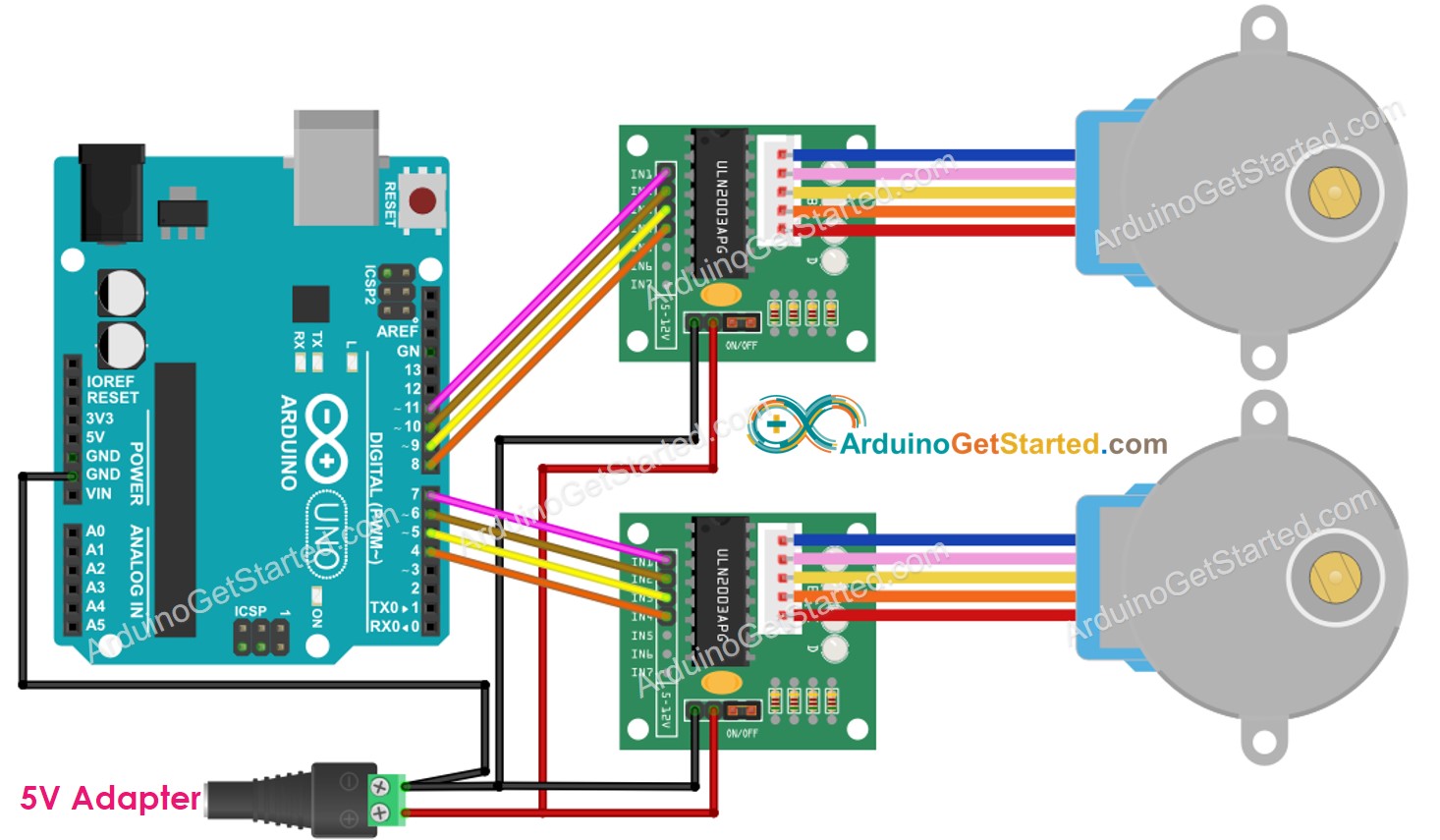
This image is created using Fritzing. Click to enlarge image
Arduino Code for two 28BYJ-48 stepper motors
Additional Knowledge
1. Stepper motor vibrates while moving
Do NOT worry if the stepper motor vibrates while moving. This is a characteristic of the stepper motor. We can reduce vibration by using the micro-stepping control method.
Also, because of this characteristic, if we control properly, the stepper motor can produce musical sounds as if it is a musical instrument. You can see this project on Arduino Project Hub.
2. Method of controlling stepper motors
- Full-step: The unit of moving is one step, which is equivalent a value of degree specified in stepper motor's datasheet or manual.
- Half-step: divides each full step into two smaller steps. The unit of moving is half of the full step. This method allows the motor move with double resolution.
- Micro-step: divides each full step into many smaller steps. The unit of moving is a fraction of the full step. The fraction can be 1/4, 1/8, 1/16, 1/32 or even more. This method allows the motor move with higher resolution. It also make motor move smoother at low speeds. The bigger dividend is, the higher resolution and the smoother motion is.
For example, If the motor's datasheet specifies 1.8 degree/step:
- Full-step: The motor can move with 1.8 degree/step <⇒ 200 steps/ revolution
- Half-step: The motor can move with 0.9 degree/step <⇒ 400 steps/ revolution
- Micro-step: The motor can move with 0.45, 0.225, 1125, 0.05625 degree/step <⇒ 800, 1600, 3200, 6400... steps/ revolution
The above code used the full-step control method.
3. Resonance Issue
This is the advanced usages. The beginners do NOT need to pay attention to it. This happens in a speed range, in which the step rate equals the motor’s natural frequency. There may be an audible change in noise made by the motor, as well as an increase in vibration. In real applications, the developer SHOULD pay attention to this issue.
Video Tutorial
We are considering to make the video tutorials. If you think the video tutorials are essential, please subscribe to our YouTube channel to give us motivation for making the videos.
WARNING
Note that this tutorial is incomplete. We will post on our Facebook Page when the tutorial is complete. Like it to get updated.
