Arduino - RGB LED
In this tutorial, we are going to learn:
- How RGB LED works.
- How to connect the RGB LED to Arduino.
- How to program Arduino to control the color of RGB LED.
Hardware Required
Or you can buy the following kits:
| 1 | × | DIYables STEM V3 Starter Kit (Arduino included) | |
| 1 | × | DIYables Sensor Kit (18 sensors/displays) |
Additionally, some links direct to products from our own brand, DIYables .
About RGB LED
The RGB LED can emit any colors by mixing the 3 basic colors red, green and blue. Actually, it consists of 3 separate LEDs red, green and blue packed together in a single case.
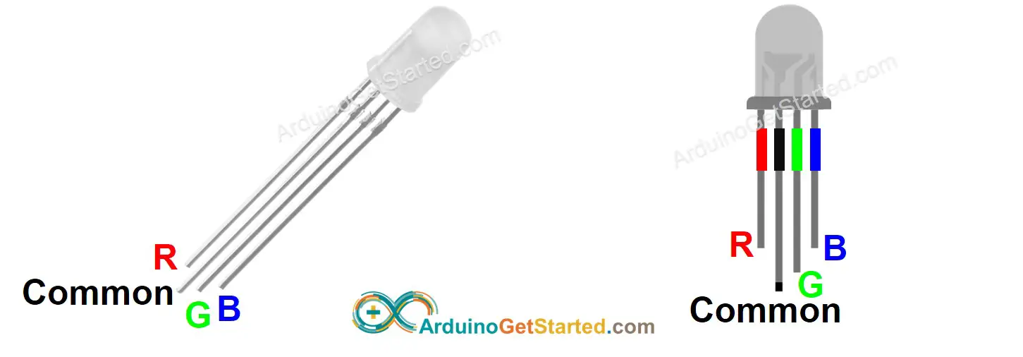
Pinout
RGB LED includes four pins:
- Common (Cathode-) pin: needs to be connected to GND (0V)
- R (red): pin is used to control red
- G (green): pin is used to control green
- B (blue): pin is used to control blue
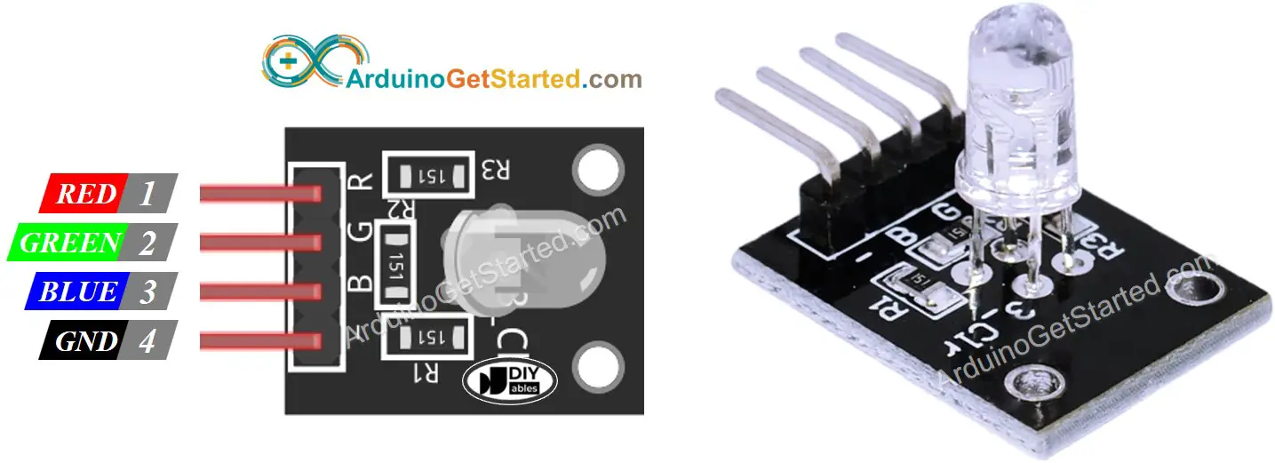
To connect RGB LED to Arduino, we need to use current-limiting resistors. This can make the wiring complex. Fortunately, we can use the RGB LED module, which already has built-in current-limiting resistors.
RGB LED Module also includes four pins:
- Common (Cathode-) pin: needs to be connected to GND (0V)
- R (red): pin is used to control red
- G (green): pin is used to control green
- B (blue): pin is used to control blue
※ NOTE THAT:
The common pin can be cathode or anode, depending of the RGB LED type. This tutorial uses a common cathode one.
How it works
In the nature of physics, a color is composed of three color values: Red (R), Grean (G) and Blue (B). Each color value ranges from 0 to 255.
The mix of three values creates 256 x 256 x 256 colors in total.
If we provide PWM signals (with duty cycle from 0 to 255) to R, G, B pins, we can makes RGB LED displays any color we want.
The duty cycle of PWM signals to R, G and B pins correspond to color values of Red (R), Grean (G) and Blue (B)
Wiring Diagram
- Wiring diagram between Arduino and RGB LED
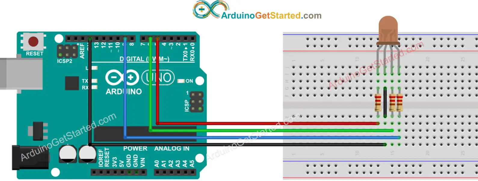
This image is created using Fritzing. Click to enlarge image
- Wiring diagram between Arduino and RGB LED module
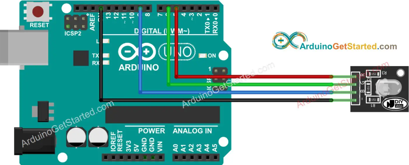
This image is created using Fritzing. Click to enlarge image
How To Control RGB LED
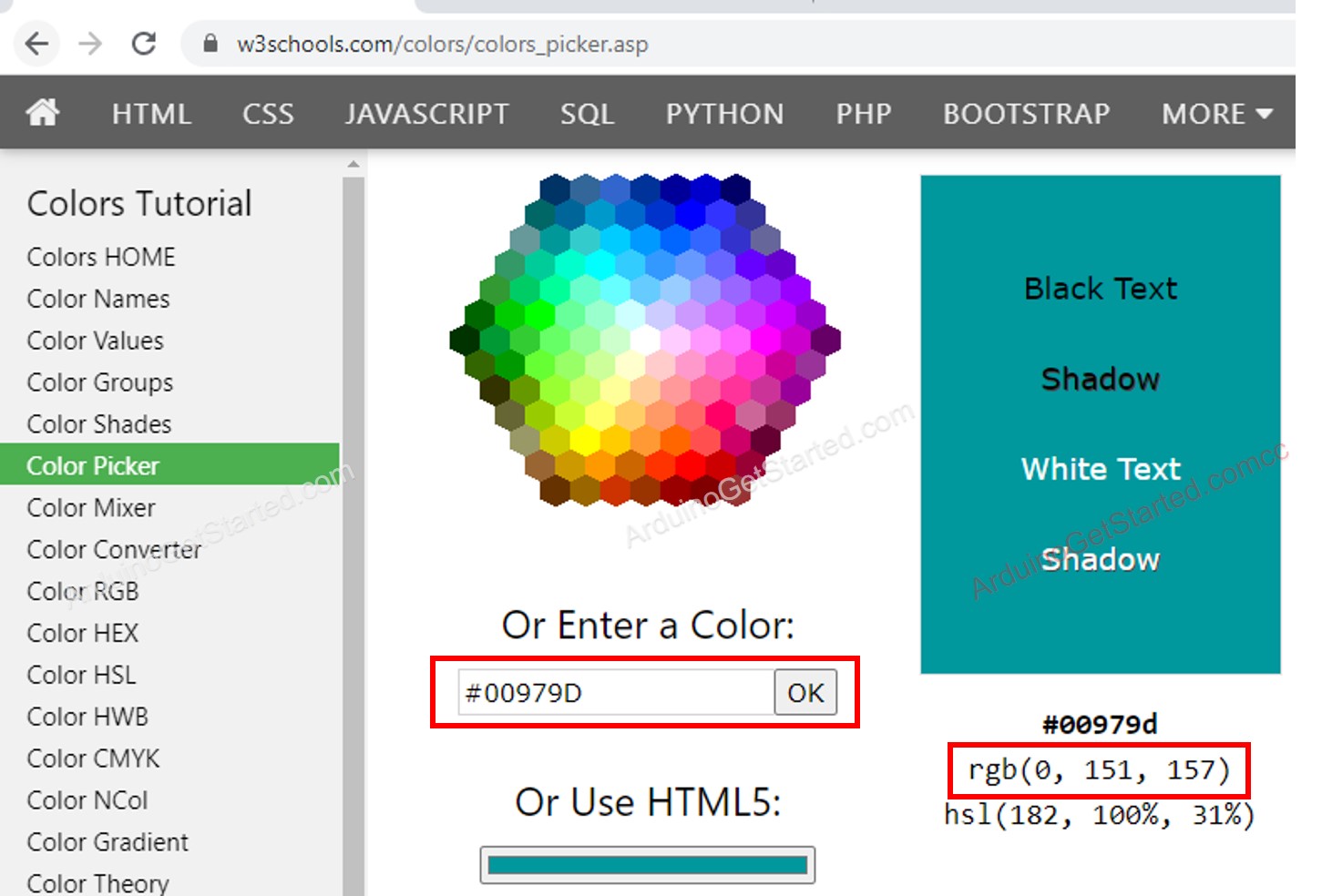
Let's lern step-by-step how to control the GRB LED to any color, for example #00979D:
- Determine which color you want to display, get its color code. Tips:
- You can pick up color code you want from the color picker
- If you want to use color in an image, use online Colors From Image tool
- Convert color code to R, G, B values using the tool from w3school. Take note these values. in this case: R = 0, G = 151, B = 157
- Define Arduino pins that connects to R, G, and B pins. For example:
- Configure these Arduino pins to the output mode
- Control LED to emit that color (#00979D → R = 0, G = 151, B = 157)
Arduino - RGB LED Example Code
The below code changes color of LED among following colors in sequence:
- #00C9CC (R = 0, G = 201, B = 204)
- #F7788A (R = 247, G = 120, B = 138)
- #34A853 (R = 52, G = 168, B = 83)
When using many colors, we could shorten the code by creating a function:
Addtional Knowledge
- For RGB LED with common Anode, you need to:
- Connect the common pin to 3.3V of Arduino.
- Change R, G and B values in analogWrite() function to 255 - R, 255 - G, and 255 - B, respectively
- A sequences of RCB LED connected together creates the RGB LED Strip. LED strip can be categorized in to the addressable LED strip and non-addressable LED Strip. We are going to make tutorials for each types of LED strip.
※ NOTE THAT:
Avoid using a single resistor in the common pin of RGB LED instead of three resistors in the other pins.
As we know, three LEDs in a single RGB package are in parallel. In ideal conditions, It is ok to use a single resistor in the common pin. However, in practice, do not use it. That is because the real world LED doesn't have the same characteristics. Three LEDs in the RGB package are NOT identical ⇒ Resistors of LEDs are different ⇒ The current is distributed unequally to each LED ⇒ Brightness is not the same and this may destroy a LED, and then destroy the other LEDs.