Disclosure: Some links in this section are Amazon affiliate links. If you make a purchase through these links, we may earn a commission at no extra cost to you. Additionally, some links direct to products from our own brand, DIYables .
About Joystick Sensor
You probably see the Joystick somewhere such as a game controller, toy controller, or even a big real machine such as an excavator controller.
The joystick is composed of two potentiometers square with each other, and one push button. Therefore, it provides the following outputs:
An analog value (from 0 to 1023) corresponding to the horizontal position (called X-coordinate)
An analog value (from 0 to 1023) corresponding to the vertical position (called Y-coordinate)
A digital value of a pushbutton (HIGH or LOW)
The combination of two analog values can create 2-D coordinates with the center are values when the joystick is in the rest position. The real direction of the coordinates can be identified simply when you run a test code (in the next part).
Some applications may use all three outputs, some applications may use some of three outputs.
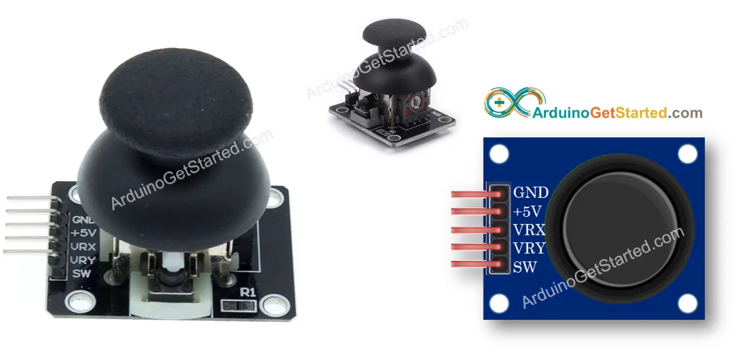
Pinout
A Joystick has 5 pins:
GND pin: needs to be connected to GND (0V)
VCC pin: needs to be connected to VCC (5V)
VRX pin: outputs an analog value corresponding to the horizontal position (called X-coordinate).
VRY pin: outputs an analog value corresponding to the vertical position (called Y-coordinate).
SW pin: is the output from the pushbutton inside the joystick. It’s normally open. If we use a pull-up resistor in this pin, the SW pin will be HIGH when it is not pressed, and LOW when it is pressed.
How It Works
When you push the joystick's thump to left/right, the voltage in the VRX pin is changed, The voltage range is from 0 to 5V (0 at left and 5v at right). The voltage value is in proportion to the position of the thump ⇒ The reading value on Arduino's analog pin is from 0 to 1023
When you push the joystick's thump to up/down, the voltage in the VRY pin is changed, The voltage range is from 0 to 5V (0 at up and 5v at down). The voltage value is in proportion to the position of the thump ⇒ The reading value on Arduino's analog pin is from 0 to 1023
When you push the joystick's thump to any direction, the voltage in both VRX and VRY pins is changed in proportion to the projection of position on each axis
When you push the joystick's thump from top to bottom, the pushbutton inside the joystick is closed, If we use a pull-up resistor in the SW pin, the output from SW pin will change from 5V to 0V ⇒ The reading value on Arduino's digital pin is changed from HIGH to LOW
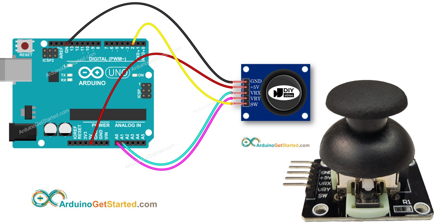
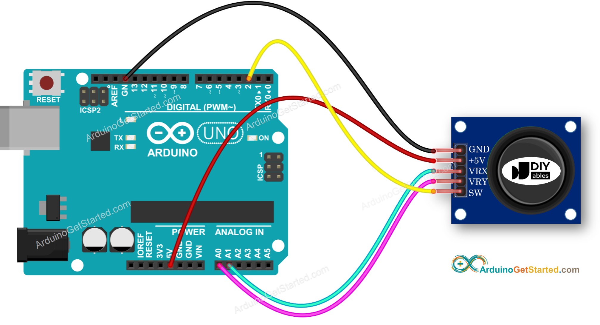
Wiring Diagram
This image is created using Fritzing. Click to enlarge image
How To Program For Joystick
The joystick has two parts: analog (X, Y axis) and digital (pushbutton)
For the analog parts (X, Y axis), it just need to read the value from analog input pin by using analogRead() function.
int xValue = analogRead(A1);int yValue = analogRead(A0);
For the digital part (pushbutton): it is a button. The most simple and convenient way is to use ezButton library. This library supports debounce for buttons and also enables an internal pull-up resistor. You can see more about button in Arduino - Button tutorial. The code will be presented in the next session in this tutorial.
After reading the values from analog pins, we may need to convert them to some controllable values. The next part will provide the example codes for this.
Arduino Code
This section will provide the following Arduino example codes:
Example code: reads analog values from joystick
Example code: reads analog values and reads the button state from joystick
Example code: converts analog value to MOVE_LEFT, MOVE_RIGHT, MOVE_UP, MOVE_DOWN commands
Example code: converts analog values to angles to control two servo motors (e.g. in pan-tilt camera)
Reads analog values from joystick
/* * Created by ArduinoGetStarted.com * * This example code is in the public domain * * Tutorial page: https://arduinogetstarted.com/tutorials/arduino-joystick */#define VRX_PIN A1 // Arduino pin connected to VRX pin#define VRY_PIN A0 // Arduino pin connected to VRY pinint xValue = 0; // To store value of the X axisint yValue = 0; // To store value of the Y axisvoidsetup() {Serial.begin(9600) ;}voidloop() {// read analog X and Y analog values xValue = analogRead(VRX_PIN); yValue = analogRead(VRY_PIN);// print data to Serial Monitor on Arduino IDESerial.print("x = ");Serial.print(xValue);Serial.print(", y = ");Serial.println(yValue);delay(200);}
Quick Steps
Copy the above code and open with Arduino IDE
Click Upload button on Arduino IDE to upload code to Arduino
Push the joystick's thump maximally to the limit, and then rotate it in a circle (clockwise or anti-clockwise)
See the result on Serial Monitor.
Newbiely | Arduino IDE 2.3.8
──
☐
✕
File
Edit
Sketch
Tools
Help
Arduino Uno
Newbiely.ino
···
8Serial.println("Hello World!");
Output
Serial Monitor
Message (Enter to send message to 'Arduino Uno' on 'COM15')
New Line
9600 baud
Ln 11, Col 1
Arduino Uno on COM15
2
While rotating the joystick' thump, keep watching the Serial Monitor
If the X value is 0, mark or memorize the current position as left ⇒ the opposite direction the right
If the Y value is 0, mark or memorize the current position as up ⇒ the opposite direction the down
Reads analog values and reads the button state from a joystick
/* * Created by ArduinoGetStarted.com * * This example code is in the public domain * * Tutorial page: https://arduinogetstarted.com/tutorials/arduino-joystick */#include <ezButton.h>#define VRX_PIN A1 // Arduino pin connected to VRX pin#define VRY_PIN A0 // Arduino pin connected to VRY pin#define SW_PIN 2 // Arduino pin connected to SW pinezButtonbutton(SW_PIN);int xValue = 0; // To store value of the X axisint yValue = 0; // To store value of the Y axisint bValue = 0; // To store value of the buttonvoidsetup() {Serial.begin(9600) ;button.setDebounceTime(50); // set debounce time to 50 milliseconds}voidloop() {button.loop(); // MUST call the loop() function first// read analog X and Y analog values xValue = analogRead(VRX_PIN); yValue = analogRead(VRY_PIN);// Read the button value bValue = button.getState();if (button.isPressed()) {Serial.println("The button is pressed");// TODO do something here }if (button.isReleased()) {Serial.println("The button is released");// TODO do something here }// print data to Serial Monitor on Arduino IDESerial.print("x = ");Serial.print(xValue);Serial.print(", y = ");Serial.print(yValue);Serial.print(" : button = ");Serial.println(bValue);}
Quick Steps
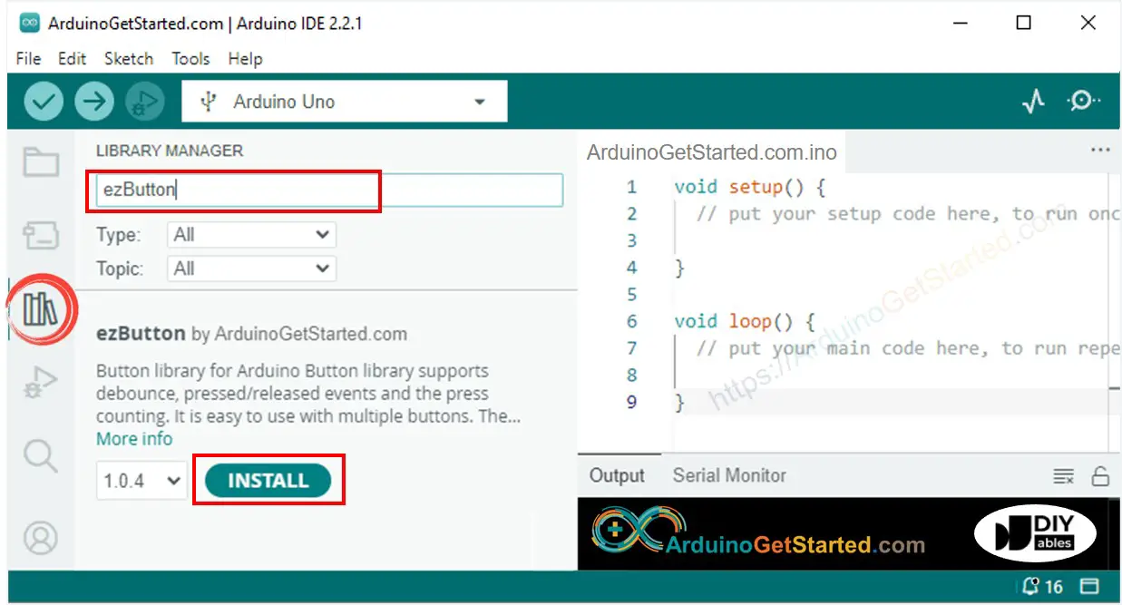
Navigate to the Libraries icon on the left bar of the Arduino IDE.
Search “ezButton”, then find the button library by ArduinoGetStarted.com
Click Install button to install ezButton library.
Copy the above code and open with Arduino IDE
Click Upload button on Arduino IDE to upload code to Arduino
Push the thump of the joystick to left/right/up/down
Push the thump of the joystick from the top
See the result on Serial Monitor.
Newbiely | Arduino IDE 2.3.8
──
☐
✕
File
Edit
Sketch
Tools
Help
Arduino Uno
Newbiely.ino
···
8Serial.println("Hello World!");
Output
Serial Monitor
Message (Enter to send message to 'Arduino Uno' on 'COM15')
New Line
9600 baud
Ln 11, Col 1
Arduino Uno on COM15
2
Converts analog value to MOVE LEFT/RIGHT/UP/DOWN commands
/* * Created by ArduinoGetStarted.com * * This example code is in the public domain * * Tutorial page: https://arduinogetstarted.com/tutorials/arduino-joystick */#define VRX_PIN A1 // Arduino pin connected to VRX pin#define VRY_PIN A0 // Arduino pin connected to VRY pin#define LEFT_THRESHOLD 400#define RIGHT_THRESHOLD 800#define UP_THRESHOLD 400#define DOWN_THRESHOLD 800#define COMMAND_NO 0x00#define COMMAND_LEFT 0x01#define COMMAND_RIGHT 0x02#define COMMAND_UP 0x04#define COMMAND_DOWN 0x08int xValue = 0 ; // To store value of the X axisint yValue = 0 ; // To store value of the Y axisintcommand = COMMAND_NO;voidsetup() {Serial.begin(9600) ;}voidloop() {// read analog X and Y analog values xValue = analogRead(VRX_PIN); yValue = analogRead(VRY_PIN);// converts the analog value to commands// reset commandscommand = COMMAND_NO;// check left/right commandsif (xValue < LEFT_THRESHOLD)command = command | COMMAND_LEFT;elseif (xValue > RIGHT_THRESHOLD)command = command | COMMAND_RIGHT;// check up/down commandsif (yValue < UP_THRESHOLD)command = command | COMMAND_UP;elseif (yValue > DOWN_THRESHOLD)command = command | COMMAND_DOWN;// NOTE: AT A TIME, THERE MAY BE NO COMMAND, ONE COMMAND OR TWO COMMANDS// print command to serial and process commandif (command & COMMAND_LEFT) {Serial.println("COMMAND LEFT");// TODO: add your task here }if (command & COMMAND_RIGHT) {Serial.println("COMMAND RIGHT");// TODO: add your task here }if (command & COMMAND_UP) {Serial.println("COMMAND UP");// TODO: add your task here }if (command & COMMAND_DOWN) {Serial.println("COMMAND DOWN");// TODO: add your task here }}
Quick Steps
Copy the above code and open with Arduino IDE
Click Upload button on Arduino IDE to upload code to Arduino
Push the thump of joystick to left/right/up/down or any direction
See the result on Serial Monitor.
Newbiely | Arduino IDE 2.3.8
──
☐
✕
File
Edit
Sketch
Tools
Help
Arduino Uno
Newbiely.ino
···
8Serial.println("Hello World!");
Output
Serial Monitor
Message (Enter to send message to 'Arduino Uno' on 'COM15')
New Line
9600 baud
Ln 11, Col 1
Arduino Uno on COM15
2
※ NOTE THAT:
At a time, there may be no command, one command or two commands (e.g. UP and LEFT at the same time)
Converts analog values to angles to control two servo motors
We are considering to make the video tutorials. If you think the video tutorials are essential, please subscribe to our YouTube channel to give us motivation for making the videos.
The below video demo uses the below code. Note that the video shows Arduino Uno R4, but it works identically for Arduino Uno R3:
You can share the link of this tutorial anywhere. Howerver, please do not copy the content to share on other websites. We took a lot of time and effort to create the content of this tutorial, please respect our work!