Arduino - Relay Shield
The relay shield has 4 relays that can be individually controlled by Arduino code. It is very easy to use. We just need to stack it on Arduino and program for it. We can use this shield to control high-power devices such as an actuator, pump, LED strip, light bulb, fan...
An alternative to the relay shield is the 4-channel relay module. The differences between a relay shield and a 4-channel relay module are below:
| Relay shield | 4-channel relay module |
|---|---|
| Does not need to do the wiring (just stack on Arduino) | Needs to do the wiring |
| Compatible with Arduino Uno, Uno Wifi, Mega only | Compatible with all Arduino board |
| Can be controlled by pre-fixed Arduino's digital pins (inflexible) | Can be controlled by any Arduino's digital pins |
In this tutorial, we are going to learn how to use the relay shield with Arduino Uno, Uno Wifi, Or Mega
Hardware Required
Or you can buy the following kits:
| 1 | × | DIYables STEM V3 Starter Kit (Arduino included) | |
| 1 | × | DIYables Sensor Kit (18 sensors/displays) |
Additionally, some links direct to products from our own brand, DIYables .
About Relay Shield
Pinout
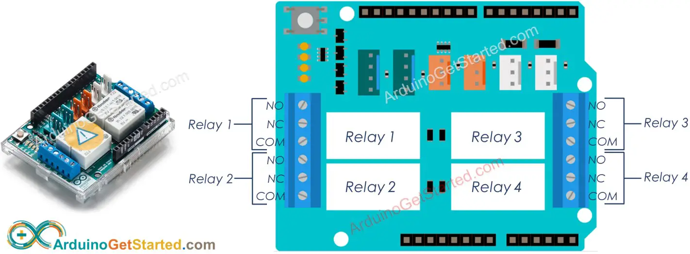
A relay shield has 4 relays named: Relay 1, Relay 2, Relay 3, Relay 4.
A relay shield has the following pins:
- Controlled pins (also called input pin, or signal pin): When stacking on Arduino, the controlled pins are internally connected to the Arduino's pins, so we do not need to do the wiring. Read the detail of each shield to know which pin controls which relay. For example, For Official Arduino Shield:
- Arduino pin 4 is internally connected to Relay 1
- Arduino pin 7 is internally connected to Relay 2
- Arduino pin 8 is internally connected to Relay 3
- Arduino pin 12 is internally connected to Relay 4
- Output pins: each relay has three pins: NC, NO, COM. These pins connect to a high-voltage device that is controlled by the relay
For detail of what is NO, NC, COM pins, how to connect relay to high-voltage, what are differences between normally closed and normally open, see Arduino - Relay tutorial
※ NOTE THAT:
- Each manufacturer designs different maximum output voltage that the relays can control. Read the specification carefully. For example, Official Arduino relay shield has a maximum voltage of 48VDC
- Each manufacturer connects relay to different Arduino pins. Read the specification or schematic to know the exact pins
- The official relay shield from Arduino connects pin 4, pin 7, pin 8 and pin 12 to relay 1, relay 2, relay 3 and relay 4, respectively.
- When using the official relay shield with Arduino Uno, if you use SPI communication to another device, You should NOT use relay 4. That is because relay 4 is connected to pin 12, which is used for SPI communication
The official relay shield also has 4 LED indicators for each relay. The LED indicators reflect the state of relays
Wiring Diagram
- Stack the relay shield on Arduino
- Connect to high-voltage devices
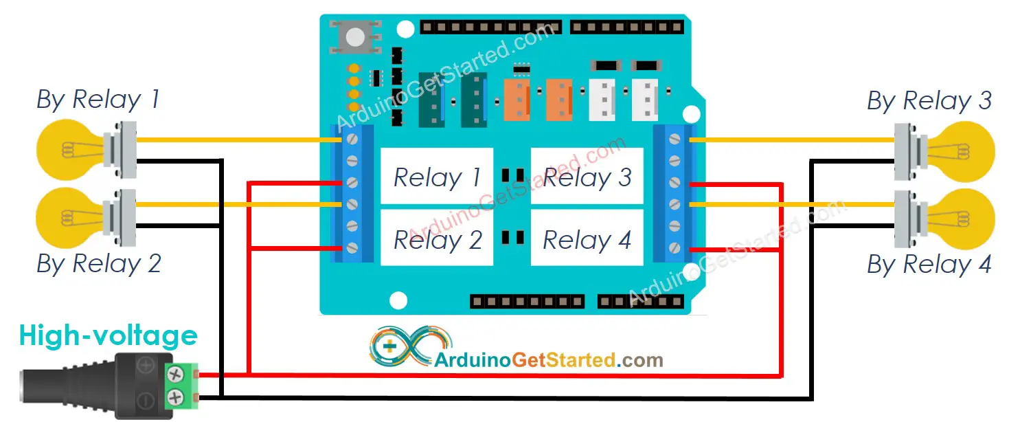
This image is created using Fritzing. Click to enlarge image
※ NOTE THAT:
- The above wiring diagram uses normally open mode. Therefore, only COM and NO are used. NC is not used.
- If 4 devices that are controlled by a relay shield use the same voltage, we can use a single high-voltage power adapter for all. However, if they use different voltages, we can use different high-voltage power adapters independently.
How To Program For 4-Channel Relay Module
- Based on the specification of the shield, define the pin map.
- Initializes the Arduino pin to the digital output mode by using pinMode() function.
- Activates relay by using digitalWrite() function to set output state to HIGH.
- Deactivate relay by using digitalWrite() function to set output state to LOW.
Arduino Code
Quick Steps
- Copy the above code and open with Arduino IDE
- Click Upload button on Arduino IDE to upload code to Arduino
- Listen the click sound on relays.
- See the result on Serial Monitor.
Video Tutorial
We are considering to make the video tutorials. If you think the video tutorials are essential, please subscribe to our YouTube channel to give us motivation for making the videos.