Arduino - DIP Switch
DIP (Dual In-line Package) switches are commonly used in electronics for configuration purposes, such as setting device addresses, enabling or disabling features, etc. In this tutorial, we are going to learn how to use the DIP switch with Arduino. In detail, we will learn:
- What is DIP switch and how it works
- How to connect the DIP switch to Arduino
- How to program Arduino to read the ON/OFF state of DIP switch
- How to program Arduino to read the integer number set by DIP switch
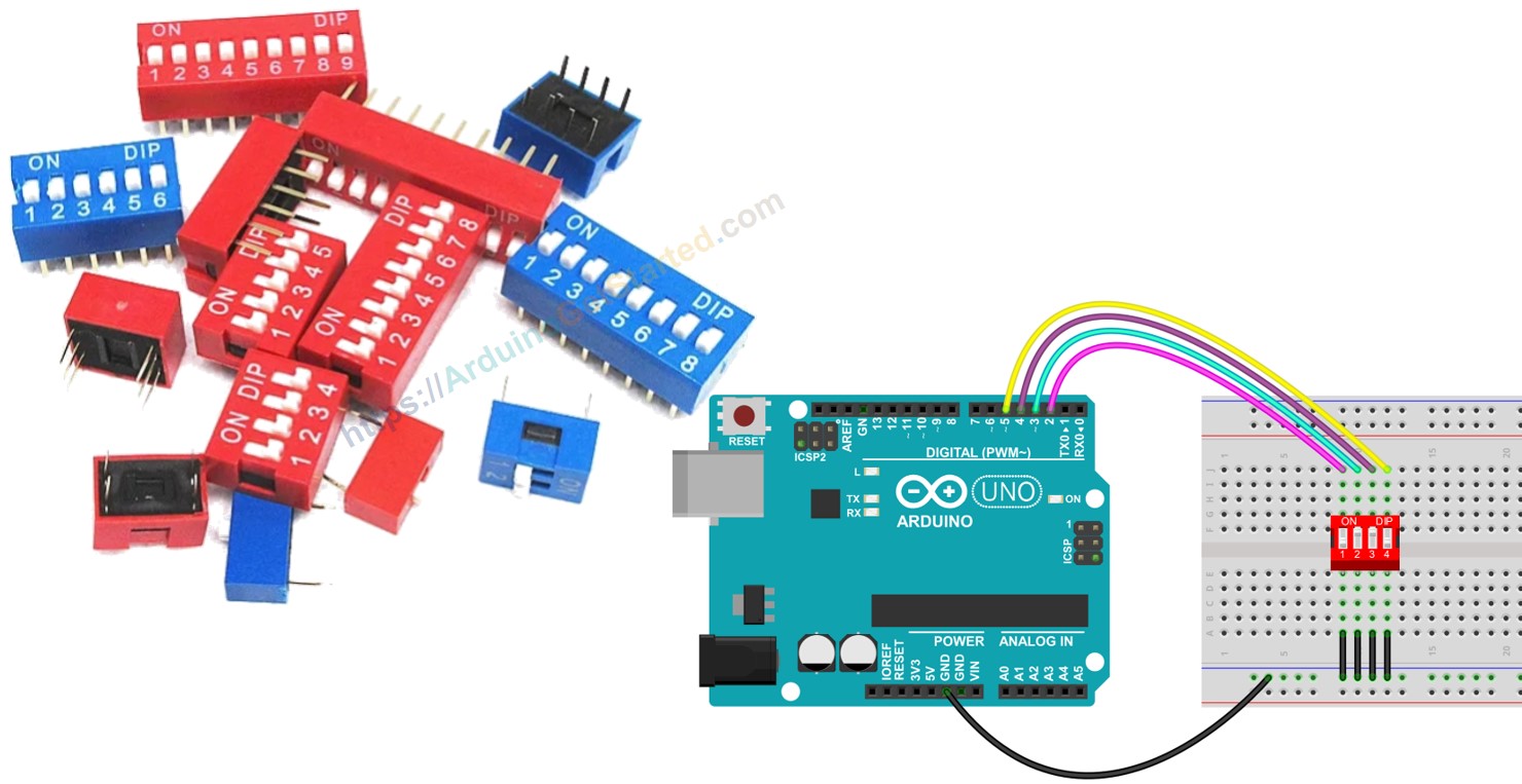
Hardware Required
Or you can buy the following kits:
| 1 | × | DIYables STEM V3 Starter Kit (Arduino included) | |
| 1 | × | DIYables Sensor Kit (18 sensors/displays) |
Additionally, some links direct to products from our own brand, DIYables .
About DIP Switch
DIP switches are primarily used for device configuration, allowing users to set parameters such as, device address, communication settings, security codes, operation mode, and system preferences across various industries and applications.
A DIP switch is made up of several small slide switches all packaged together. Each of these slide switches is referred to as a "position". DIP switches come in various types depending on the number of positions they have. For instance, there are 2-position DIP switches, 4-position DIP switches, 5-position DIP switches, 6-position DIP switches, 8-position DIP switches, and 10-position DIP switches.
A DIP switch can represent for a configurable number a configurable number. Each position on the switch corresponds to a bit of the number. By toggling the positions between ON and OFF, we can set the desired number we want.
Pinout
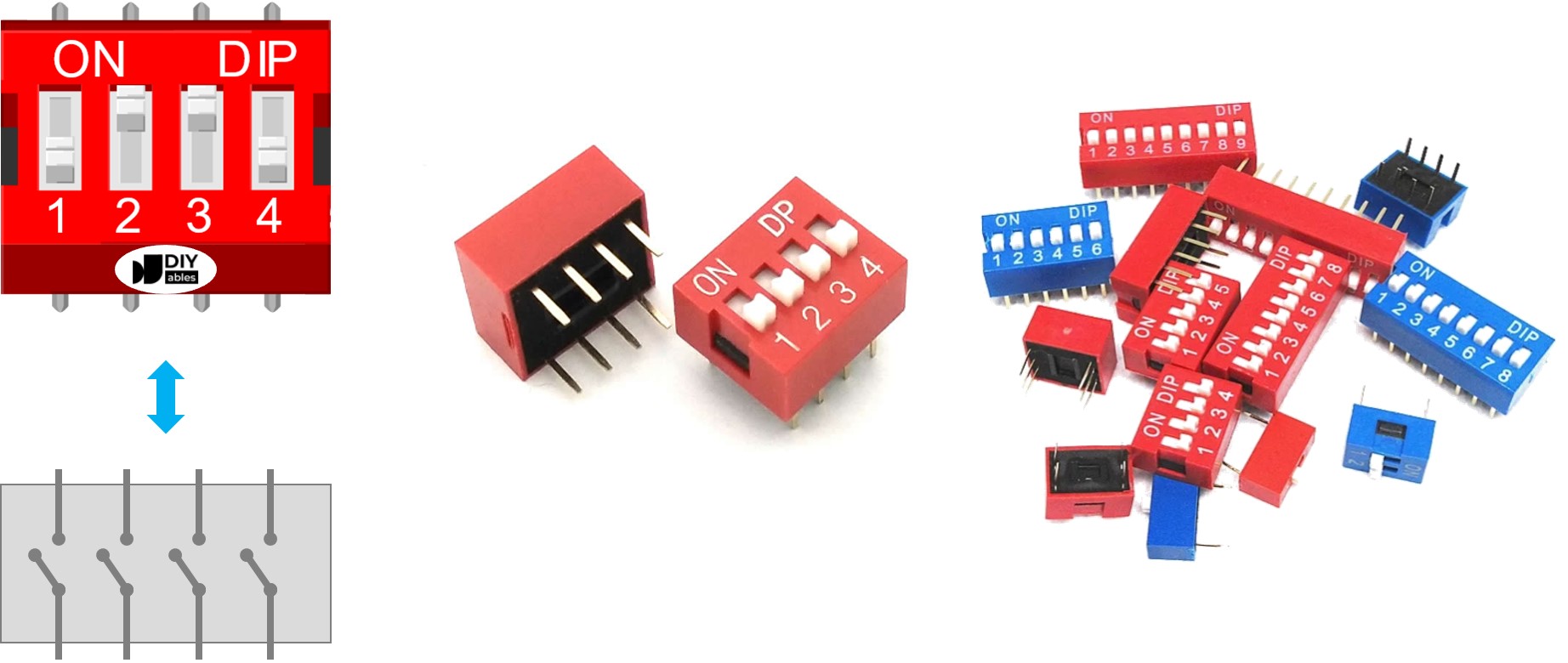
A DIP switch consists of dual rows of pins, with the quantity of pins in each row corresponding to the number of switch positions available. For example, a 4-position DIP switch comprises a total of 8 pins, evenly distributed with 4 pins on each side. Within the DIP switch assembly, every pair of opposing pins constitutes a slide switch. It's noteworthy that distinguishing between pins on the two sides isn't necessary since they are interchangeable.
How It Works
In the DIP switches, when a switch is in the ON position, it means that the switch is closed. This means that the electrical connection is made, allowing current to flow through the switch.
Conversely, when a switch is in the OFF position, it means that the switch is open. In this state, the electrical connection is broken, and current cannot flow through the switch.
So, to clarify:
- ON position: Closed circuit, allowing current to flow.
- OFF position: Open circuit, blocking current flow.
When we connect a side of a switch to GND, the other to Arduino pin, then configure Arduino pin as pull-up digital input, the below table shown the relation between switch position and the values read from Arduino:
| DIP switch position | Binary representation | Circuit state | Arduino pin state |
|---|---|---|---|
| ON | 1 | CLOSED | LOW |
| OFF | 0 | OPEN | HIGH |
In the next parts, we will use 4-position DIP switch for example. You can easily to adapt for 2-position DIP switches, 3-position DIP switches, 5-position DIP switches, 6-position DIP switches, 8-position DIP switches, and 10-position DIP switches...
Wiring Diagram
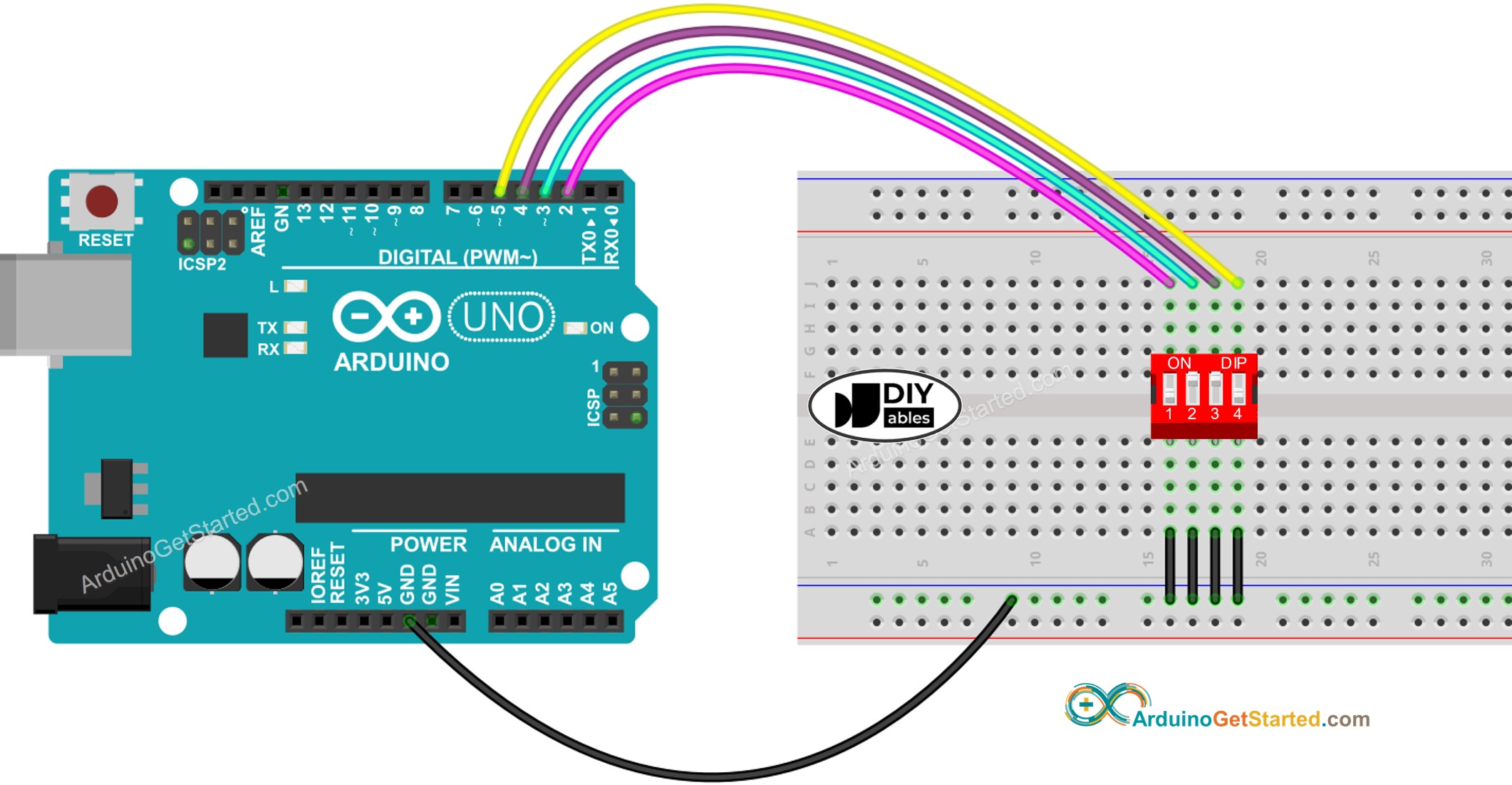
This image is created using Fritzing. Click to enlarge image
Arduino Code - DIP Switch
We will learn through two pieces of code:
- Reading the ON/OFF state of individual position on the DIP switch.
- Encoding the positions into a number.
Arduino code - Reading the ON/OFF state of the DIP switch
Quick Steps
- Do wiring as above wiring diagram
- Connect Arduino to PC via USB cable
- Open Arduino IDE
- Select the right board and port
- Click Upload button on Arduino IDE to upload code to Arduino
- Switch each position on the DIP Switch to ON one by one.
- See the result on Serial Monitor.
Arduino code - Encoding the states of DIP switch into a number
Quick Steps
- Upload the above code to Arduino
- Switch each position on the DIP switch to ON one by one.
- See the result on Serial Monitor, it look like below.
Please note that the value depends on positions of each slide switches. The below table shows the mapping between ON/OFF position and the integer value for 4-position DIP switch:
| Position-1 | Position-2 | Position-3 | Position-4 | Binary Value | Decimal Value |
|---|---|---|---|---|---|
| OFF | OFF | OFF | OFF | 0000 | 0 |
| OFF | OFF | OFF | ON | 0001 | 1 |
| OFF | OFF | ON | OFF | 0010 | 2 |
| OFF | OFF | ON | ON | 0011 | 3 |
| OFF | ON | OFF | OFF | 0100 | 4 |
| OFF | ON | OFF | ON | 0101 | 5 |
| OFF | ON | ON | OFF | 0110 | 6 |
| OFF | ON | ON | ON | 0111 | 7 |
| ON | OFF | OFF | OFF | 1000 | 8 |
| ON | OFF | OFF | ON | 1001 | 9 |
| ON | OFF | ON | OFF | 1010 | 10 |
| ON | OFF | ON | ON | 1011 | 11 |
| ON | ON | OFF | OFF | 1100 | 12 |
| ON | ON | OFF | ON | 1101 | 13 |
| ON | ON | ON | OFF | 1110 | 14 |
| ON | ON | ON | ON | 1111 | 15 |
Video Tutorial
We are considering to make the video tutorials. If you think the video tutorials are essential, please subscribe to our YouTube channel to give us motivation for making the videos.