Arduino - Motion Sensor
When you approach some places that the doors are automatically opened/closed, the light bulbs are automatically turned on/off or escalator is automatically activated, have you ever make a question: “How can it do that?” ? If yes, this tutorial not only answers but also tells you how to make it. Let's start!
In this tutorial, we are going to learn:
- How HC-SR501 motion sensor works
- How to connect HC-SR501 motion sensor to Arduino
- How to program Arduino to read the state from the HC-SR501 motion sensor
- How to use Arduino and HC-SR501 motion to detect the human entrance and take action based on it.
Hardware Required
Or you can buy the following kits:
| 1 | × | DIYables STEM V3 Starter Kit (Arduino included) | |
| 1 | × | DIYables Sensor Kit (18 sensors/displays) |
Additionally, some links direct to products from our own brand, DIYables .
About HC-SR501 Motion Sensor
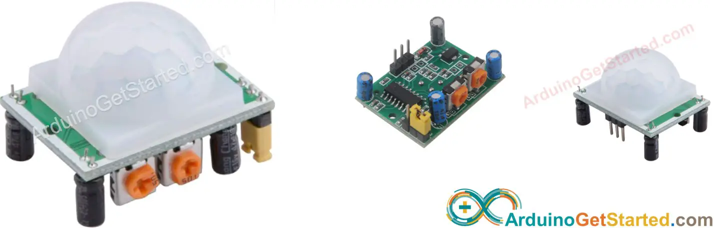
HC-SR501 PIR sensor is a sensor that can detect the motion of humans (or animals). It's widely used to detect the presence of humans in many applications (automatically turning ON/OFF light bulb, opening/closing the door, activating/deactivating escalator, detecting an intruder ...)
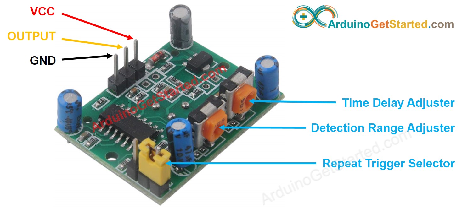
Pinout
The HC-SR501 motion sensor has 3 pins:
- GND pin: needs to be connected to GND (0V)
- VCC pin: needs to be connected to VCC (5V)
- OUTPUT pin: is an output pin: LOW when no motion is detected, HIGH when motion is detected. This pin needs to be connected to Arduino's input pin.
The HC-SR501 also has one jumper and two potentiometers, which are used to adjust the sensor's setting. Firstly, keep the default setting. The detail is described in the Advanced Uses section.
How It Works
The HC-SR501 sensor detects motion based on the change of infrared radiation from the moving object. To be detected by the HC-SR501 sensor, the object must meet two conditions:
- Is moving or shaking
- Is emitting the infrared way.
So:
- If an object is moving but NOT emitting the infrared ray (e.g, robot or vehicle toy), it is NOT detected by the sensor.
- If an object is emitting infrared ray but NOT moving (e.g, a person stands still without moving), it is NOT detected by the sensor.
Humans and animals naturally emit the infrared. Therefore, the sensor can detect the movement of humans and animals.
OUTPUT pin's state:
- When there is NO human (or animal) moving in the detected range of the sensor, the OUTPUT pin of sensor is LOW.
- When there is human (or animal) moving into the detected range of the sensor, the OUTPUT pin of sensor is changed from LOW to HIGH (⇒ motion detected).
- When there is human (or animal) going away from the detected range of the sensor, the OUTPUT pin of sensor is changed from HIGH to LOW (⇒ motion ended).
The above video illustrates how the motion sensor works in principle. In practice, the motion sensor works a little bit different, depending on the sensor setting (described in the Advanced Uses section)
Detect the Presence of Human
The sensor itself does NOT detect the presence of humans, the sensor just detects the motion. We use Arduino (or MCU) to deduce the presence of humans basing on motion detection from the sensor, according to the following rule:
- If motion is detected, the humans are present
- If motion is NOT detected, the humans are NOT present
This rule is incorrect in a practical case: the humans are present in sensor range but NOT moving. The motion is NOT detected. The Arduino (or MCU) deduces that human is NOT present.
For example, your meeting room uses the motion sensor to automatically turn on/off light, the light is turned on automatically when people move into the room. During the meeting time, if everybody sits still without moving, motion is NOT detected ⇒ human is NOT present ⇒ light is turned off automatically. To turn on the light, someone needs to move.
However, this issue is NOT serious and the sensor is cheap. Therefore, The sensor's widely used to detect the human in many application.
Arduino - HC-SR501 Motion Sensor
When an Arduino's pin is configured as a digital input, It can read the state (LOW or HIGH) of anything it connected to.
By connecting the Arduino's pin with the OUTPUT pin of the HC-SR501 sensor, we can use the Arduino code to check the value of the OUTPUT pin to detect the motion.
Wiring Diagram
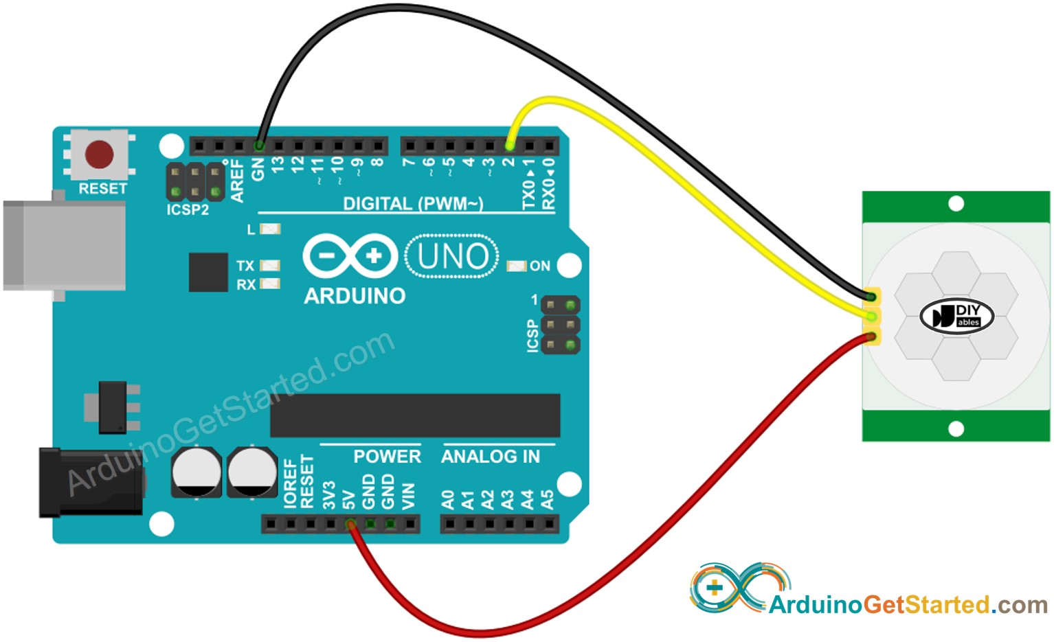
This image is created using Fritzing. Click to enlarge image
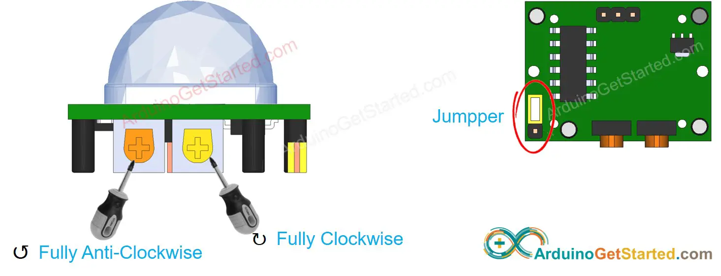
Initial Setting
| Time Delay Adjuster | Screw it in anti-clockwise direction fully. |
| Detection Range Adjuster | Screw it in clockwise direction fully. |
| Repeat Trigger Selector | Put jumper as shown on the image. |
How To Program For Motion Sensor
- Configure an Arduino's pin to the digital input mode by using pinMode() function
- Read state of sensor's OUTPUT pin by using digitalRead() function.
- Detect motion start (pin's state change from LOW to HIGH)
- Detect motion stop (pin's state change from HIGH to LOW)
Arduino Code
Quick Steps
- Copy the above code and open with Arduino IDE
- Click Upload button on Arduino IDE to upload code to Arduino
- Open Serial Monitor
- Move your hand in front of sensor range
- See the output in Serial Monitor
Arduino UNO R4 with HC-SR501 Motion Sensor - Video Tutorial
The below is a step-by-step video tutorial demonstrating how to use the HC-SR501 motion sensor with the Arduino UNO R4. At the end of the video, you will see how to make an automated open door system with a servo and buzzer using the code below:
Advanced Uses
As mentioned above, we can change adjust the sensor's setting via one jumper and two potentiometers.
Detection Range Adjuster
This potentiometer is used to adjust the detection range (approximately 3 meters to 7 meters).
- If it is screwed fully in the clockwise direction, the detection range is approximately 3 meters.
- If it is screwed fully in the anti-clockwise direction, the detection range is approximately 7 meters.
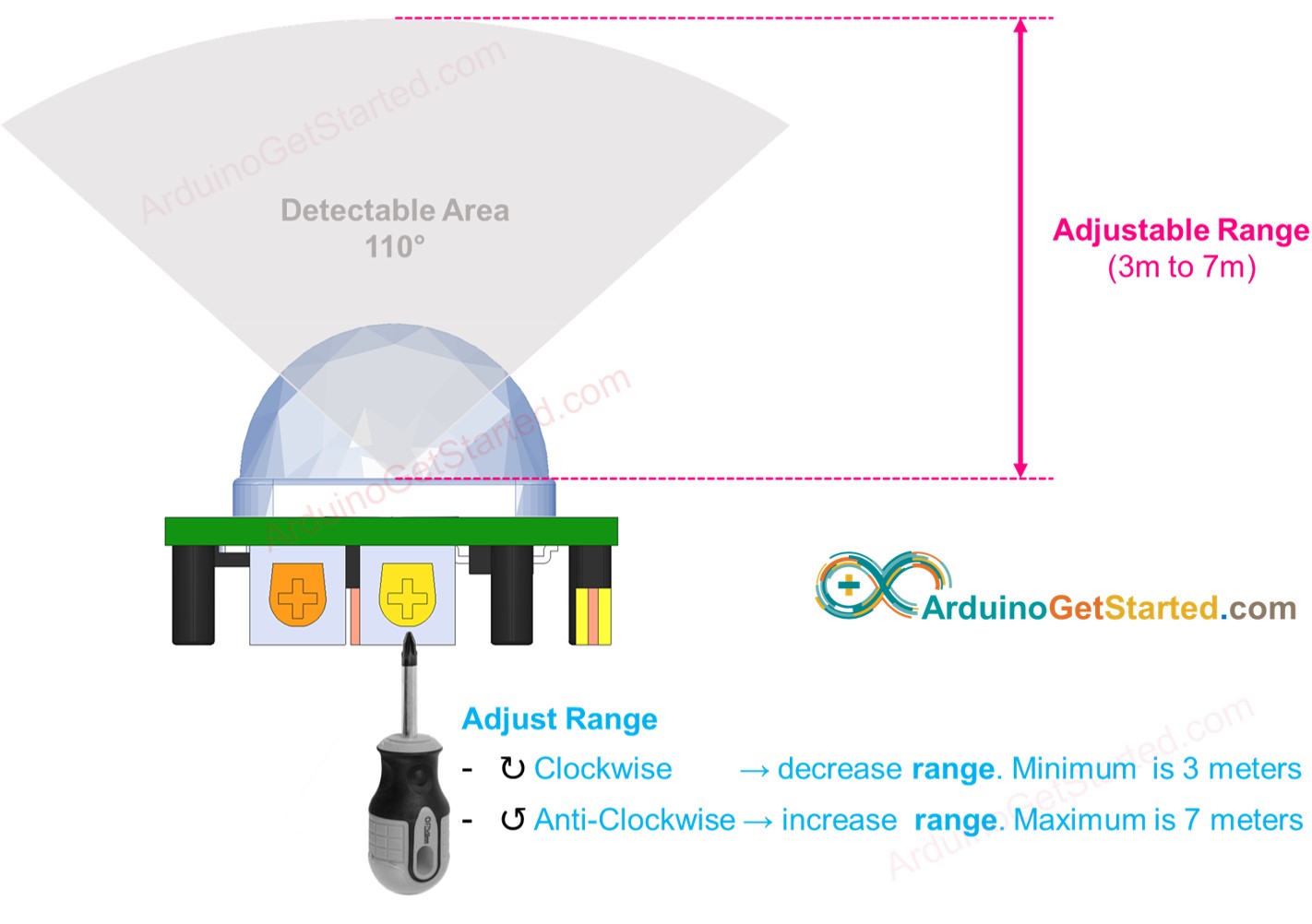
We can adjust the potentiometer to achieve the desired range (a value in between 3m and 7m)
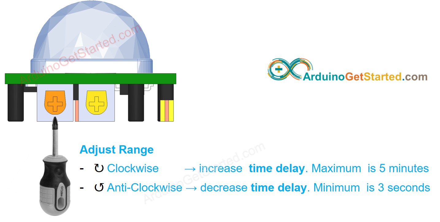
Time Delay Adjuster
This potentiometer is used to adjust the time delay.
- If it is screwed fully in the clockwise direction, the time delay is approximately 5 minutes.
- If it is screwed fully in the anti-clockwise direction, the time delay is approximately 3 seconds.
The meaning of time delay is explained in combination with Repeat Trigger in the next part.
Repeat Trigger Selector
There is a jumper, which is used to select trigger modes: single trigger or repeatable trigger.
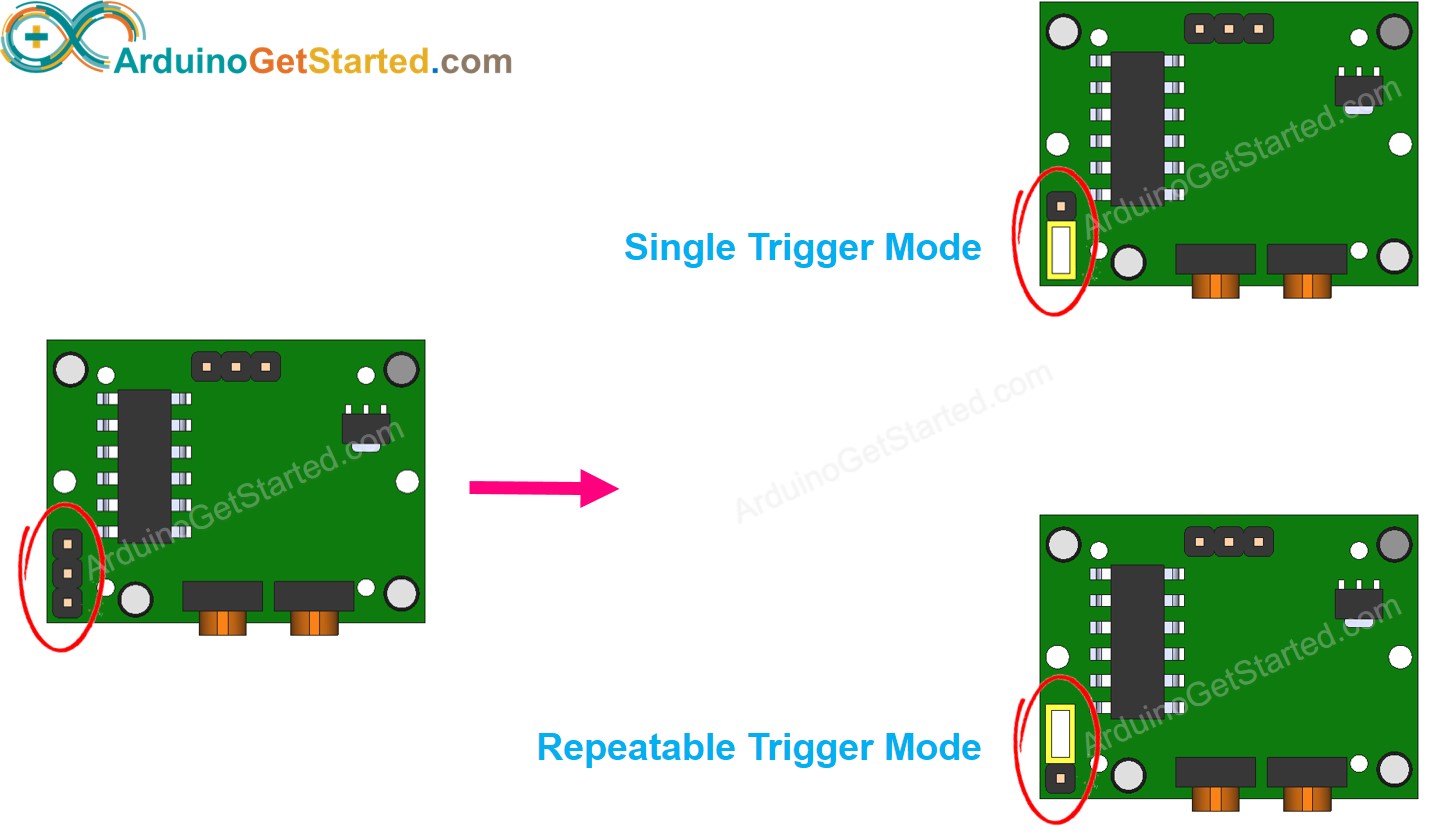
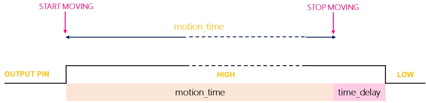
Let's call time delay setting (is set via Time Delay Adjuster) is time_delay. Suppose that you keep moving in the range of the sensor in a long time (called motion_time) (several times longer than time_delay)
- Single trigger mode: OUTPUT pin's state is toggled between LOW and HIGH several times. HIGH duration is equal to time_delay. LOW duration is fixed to 3 seconds.
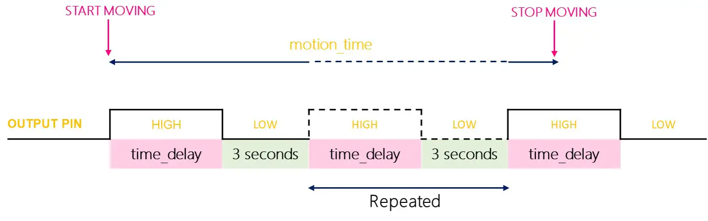
- Repeatable trigger mode: OUTPUT pin's state keeps HIGH during (motion_time + time_delay).
Testing
To see how the trigger modes work, let's make a test. Set Time Delay Adjuster fully anti-clockwise to the time delay to 3 seconds.
- Single trigger mode:
- Set jumper to select the single trigger mode
- Keep moving your hand in front of the sensor for about 10 seconds.
- Move your hand out of sensor's range
- Wait for 3 seconds, you will see the output in serial monitor as follow:
- Repeatable trigger mode:
- Set jumper to select Repeatable trigger mode
- Keep moving your hand in front of the sensor for about 10 seconds.
- Move your hand out of sensor's range
- Wait for 3 seconds, you will see the output in serial monitor as follow:
- We turn on or activate devices/machines right after human is present
- We do NOT turn off or deactivate devices/machines immediately right after human is NOT present. We turn off or deactivate devices/machines after a timeout.
- On motion sensor: min is 3 seconds and max id 5 minutes. done via Time Delay Adjuster
- On Arduino Code: any value, done by coding
As we can see, in a single trigger mode, the sensor triggers two or three times. In the repeatable trigger mode, the sensor triggers only one time.
※ NOTE THAT:
In both cases, during LOW (3 seconds) time (the fixed and unadjustable value), the sensor is NOT able to detect any motion. In other words, the sensor is blocked in this period. In practice, it does NOT cause any problem.
It is recommended to use the repeatable trigger mode.
In many real applications:
How To Use Time Delay
When human is detected NOT present, the automation system will take action after a time delay.
The time delay can be set on the motion sensor and Arduino code:
If we do NOT set a timeout in the Arduino code, the timeout is equal to the time delay in the sensor's setting.
If we set a timeout in the Arduino code, the timeout is the sum of time delay in the sensor's setting and time delay in the Arduino code.
Setting time delay in Arduino code
Suppose that the repeatable trigger mode is set. Delay in this code is set to 30 seconds. It means the delay time is equal to 30 seconds plus time_delay, which is set on the sensor's setting (via Time Delay Adjuster).
Challenge Yourself
Use the motion sensor to do one of the following projects:
- Automatically turn on the light when you enter into your room and turn off the light after you leave 30 seconds. Hint: Refer to Arduino - Relay.
- Automatically make alarm when someone approaches your valuable stuff. Hint: Refer to Arduino - Piezo Buzzer.