Arduino - LED - Blink
In this tutorial, we learn how to control LED with using Arduino, how to program for Arduino to turn LED on/off, and how to blink LED
Hardware Required
Or you can buy the following kits:
| 1 | × | DIYables STEM V3 Starter Kit (Arduino included) | |
| 1 | × | DIYables Sensor Kit (18 sensors/displays) |
Additionally, some links direct to products from our own brand, DIYables .
Buy Note: To simplify the wiring process, we recommend using the LED Module, which comes with a built-in resistor.
About LED
Pinout
LED includes two pins:
- Cathode(-) pin: needs to be connected to GND (0V)
- Anode(+) pin: is used to control LED's state

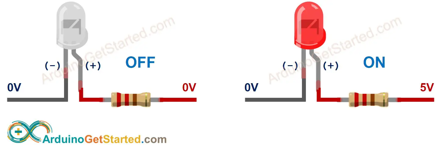
How It Works
After connecting the cathode(-) to GND:
- If connecting GND to the anode(+), LED is OFF.
- If connecting VCC to the anode(+), LED is ON.
Besides, if generating a PWM signal to the anode(+), the brightness of LED is changed according to PWM value ( described in detail in this tutorial)
※ NOTE THAT:
- For most of LED, we need to use a resistor. The resistor can be placed between the anode(+) and VCC or between the cathode(-) and GND. The value of the resistor depends on the specification of the LED.
- Some kinds of LEDs have a built-in resistor. We may not need to use a resistor for those kinds of LEDs.
Arduino - LED
When an Arduino's pin is configured as a digital output, the pin's voltage can be programmatically set to GND or VCC value.
By connecting the Arduino's pin to LED's anode(+) pin (via a resistor), we can programmatically control LED's state.
Wiring Diagram
We are going to run through two examples:
- Example code controls the built-in LED on Arduino/Genuino UNO.
- Modifying Arduino Code controls the external LED.
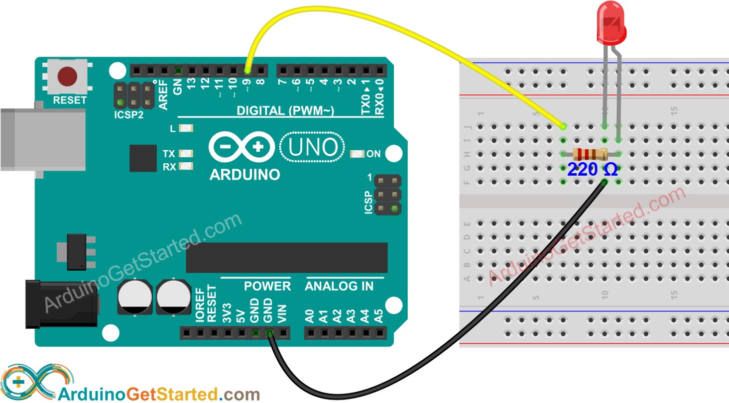
This image is created using Fritzing. Click to enlarge image
How To Program
- Configure an Arduino's pin to the digital output mode by using pinMode() function. For example, pin 9:
Arduino Code
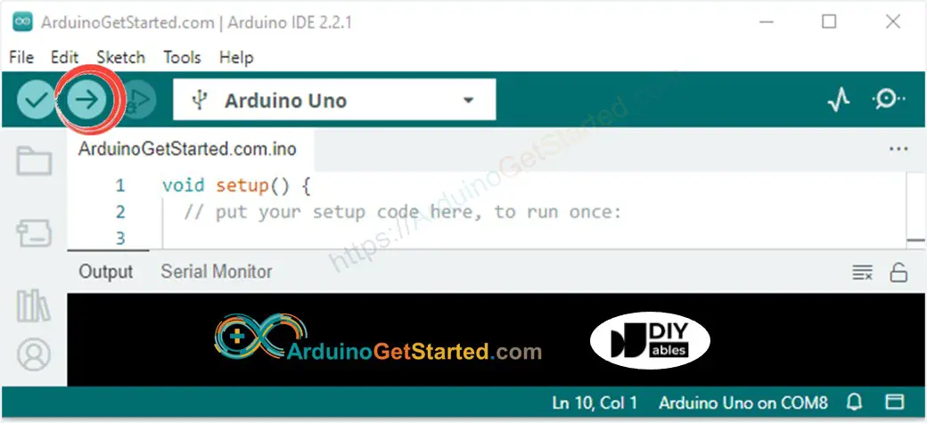
Quick Steps
- Connect Arduino to PC via USB cable
- Open Arduino IDE, select the right board and port
- Copy the below code and paste it to the Arduino IDE
- Click Upload button on Arduino IDE to upload code to Arduino
- See the result: The built-in LED toggles between ON/OFF periodically every second.
Code Explanation
Read the line-by-line explanation in comment lines of code!
※ NOTE THAT:
The above code uses the delay(). This function blocks Arduino from doing other tasks during the delay time. If your project requires to do some tasks, avoid blocking Arduino by using the non-blocking method for Arduino.
Modifying Arduino Code
Modifying code to control the external LED
Quick Steps
- Connect LED to Arduino via the above wiring diagram.
- Modify code:
- Change LED_BUILTIN to 9
- Change the delay from 1000 ms to 500 ms
- Click Upload button on Arduino IDE to upload code to Arduino
- See the result: LED switches between ON/OFF periodically. The LED blinks faster.
※ NOTE THAT:
This tutorial provides in-depth knowledge that helps you understand the working principle. To make it easy, you can use Arduino - LED library.
Video Tutorial
We are considering to make the video tutorials. If you think the video tutorials are essential, please subscribe to our YouTube channel to give us motivation for making the videos.
Challenge Yourself
- Connect LED to another pin of Arduino and change the blink time.
- Turn on/off LED by button. Hint: Refer to Arduino - Button.
Additional Knowledge
- Pin 0 to pin 13
- Pin A0 to pin A5
※ NOTE THAT:
At a time, one pin can take only one task. If you already used a pin for another task (e.g, digital input, analog input, PWM, UART...), you should NOT use it as digital output to control LED. For example, if we use Serial.println() function, we should NOT use pin 0 and 1 for any other purpose because these pins are used for Serial.
Extendability
This tutorial shows how to use the output pin of Arduino to control an LED. We can apply this code to control ON/OFF any devices, even big machines.
※ NOTE THAT:
for devices/machines that use a high power supply ( > 5v) and/or high-current consumption, we need to use a relay between output pin and devices/machines - see Arduino - Relay.