Arduino - Buzzer
In this tutorial, we are going to learn how to program Arduino to control a 12V active buzzer to produce a loud sound. If you want to control 5V active/passive buzzer, please check out this Arduino Piezo Buzzer tutorial
Hardware Required
Or you can buy the following kits:
| 1 | × | DIYables STEM V3 Starter Kit (Arduino included) | |
| 1 | × | DIYables Sensor Kit (18 sensors/displays) |
Additionally, some links direct to products from our own brand, DIYables .
About 12V Active Buzzer
The 12V Active Buzzer can produce a loud sound, which is suitable for the alarming system.
Pinout
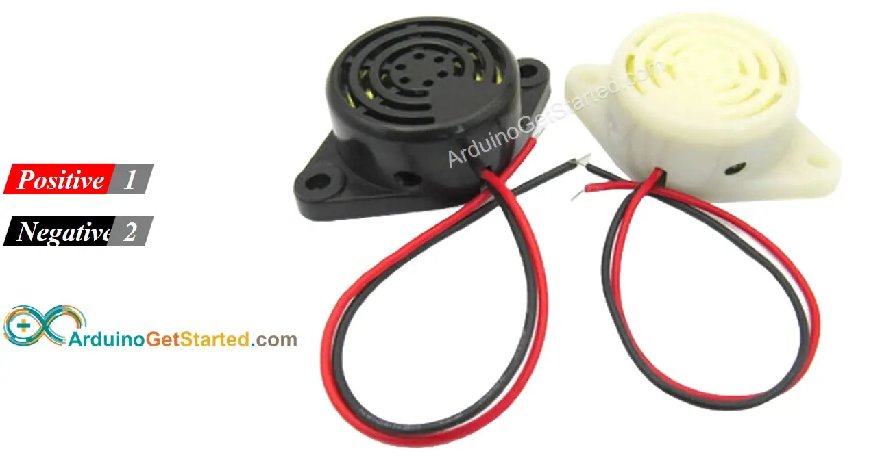
12V Active Buzzer usually has two pins:
- Negative (-) pin (black): needs to be connected to GND of DC power supply
- Positive (+) pin (red): needs to be connected to 12V of DC power supply
How to Control 12V Active Buzzer
If 12V active buzzer is powered by 12V power supply, it make sound. To control a 12V active buzzer, we need to use a relay in between Arduino and 12V active buzzer. Arduino can control the 12V active buzzer via the relay. If you do not know about relay (pinout, how it works, how to program ...), learn about relay in the Arduino - Relay tutorial
Wiring Diagram
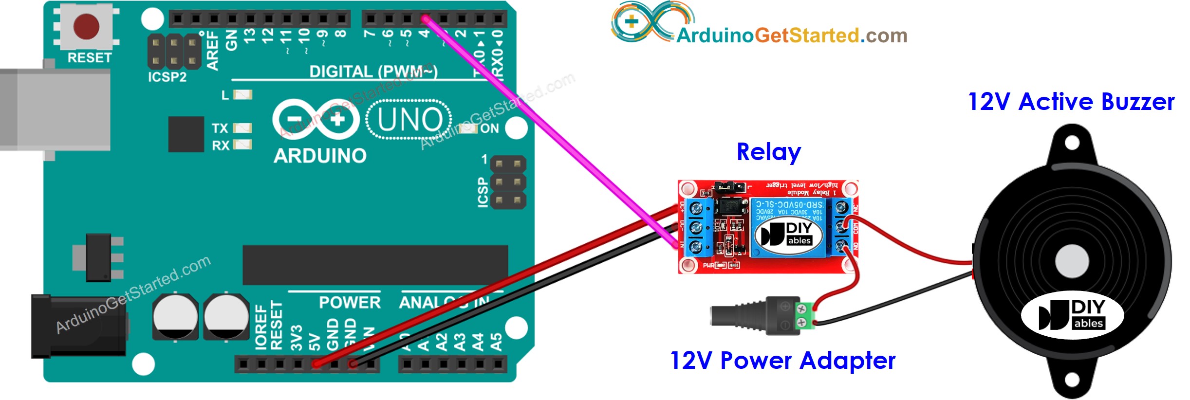
This image is created using Fritzing. Click to enlarge image
Arduino Code
The below code repeatedly turns the 12V active buzzer ON in two seconds and OFF in five seconds,
Quick Steps
- Connect Arduino to PC via USB cable
- Open Arduino IDE, select the right board and port
- Copy the above code and open with Arduino IDE
- Click Upload button on Arduino IDE to upload code to Arduino
- See the 12V active buzzer's state
Code Explanation
Read the line-by-line explanation in comment lines of code!
Video Tutorial
We are considering to make the video tutorials. If you think the video tutorials are essential, please subscribe to our YouTube channel to give us motivation for making the videos.