Arduino - LED Matrix
LED matrix display, also known as LED display, or dot matrix display, are wide-used. In this tutorial, we are going to learn:
- LED matrix
- How to connect Arduino to 8x8 LED matrix
- How to connect Arduino to 32x8 LED matrix
- How to connect Arduino to display text, numbers, and animated effects on the LED matrix.
After that, you can easily adapt the code for other LED matrices such as 16x8 LED matrix, 64x8 LEd matrix ...
Hardware Required
Or you can buy the following kits:
| 1 | × | DIYables STEM V3 Starter Kit (Arduino included) | |
| 1 | × | DIYables Sensor Kit (18 sensors/displays) |
Additionally, some links direct to products from our own brand, DIYables .
About LED Matrix
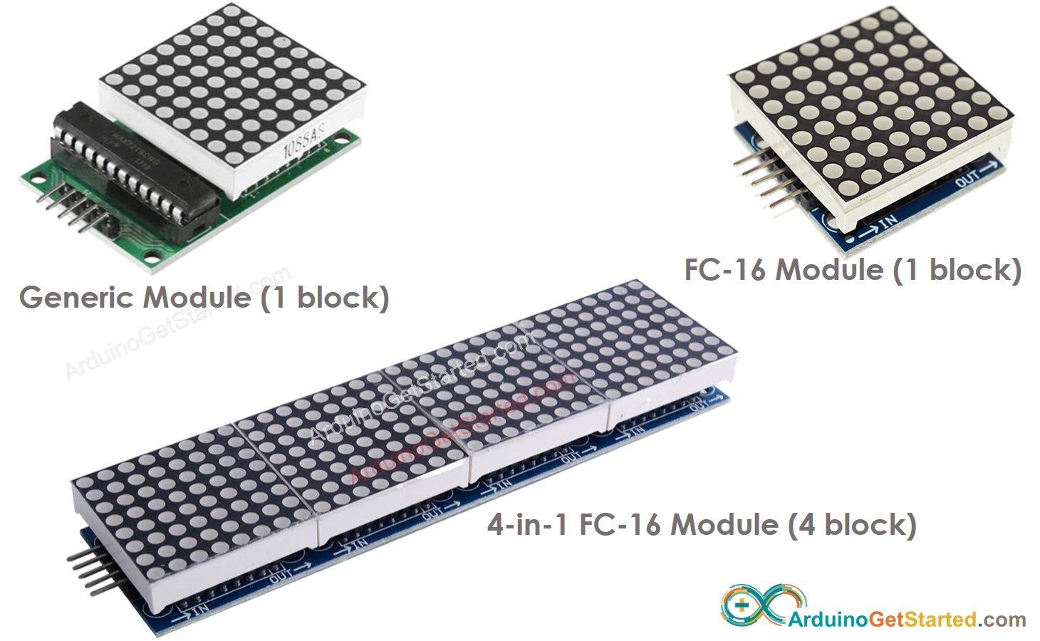
There are many kinds of LED Matrix. With Arduino, the MAX7219-based LED matrix is widely used. MAX7219-based LED matrix has the following features:
- A base unit of an LED matrix is a block
- Each block has an 8x8 LED matrix (64 LED) and a MAX7219 driver.
- There are two popular block forms: the generic module and the FC-16 module.
- A LED matrix can be composed of a single block or multiple blocks in a daisy-chain
- You can buy a pre-built multiple-block LED Matrix (e.g. 4-in-1, 8-in-1)
- You can also buy multiple blocks and wire them to form a LED matrix with the desired size.
- You will declare the size of the LED matrix you use in the Arduino code.
Pinout
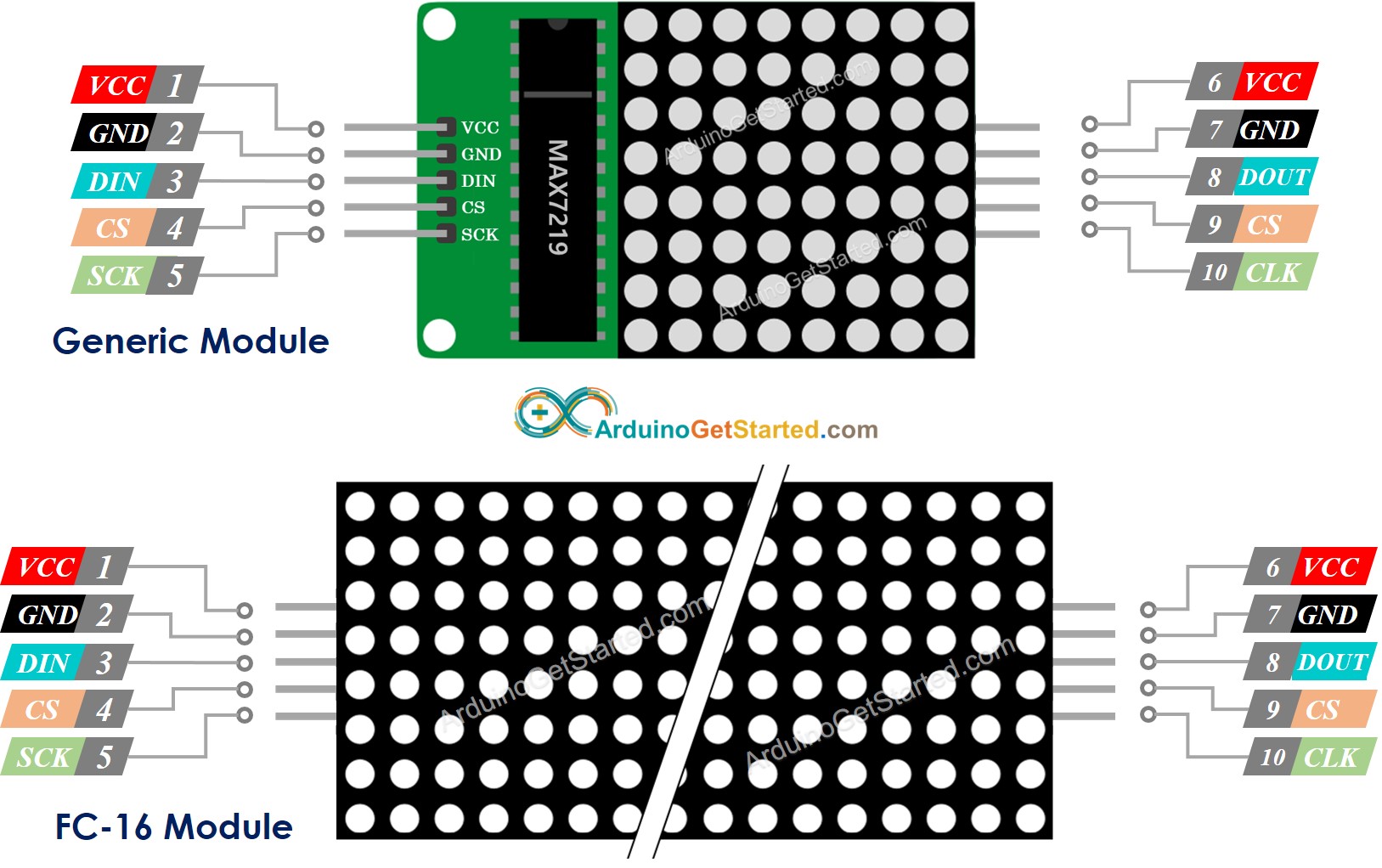
A LED Matrix is formed by a single or multiple blocks. Each block includes two groups of pins:
- Input pins group:
- VCC: connected to 5V.
- GND: connected to GND.
- DIN is the Data pin, Connect it to SPI MOSI pin of the Arduino.
- CS: Chip Select, Connect it to any digital pin of the Arduino.
- CLK: Clock pin, Connect it to SPI CLK pin of the Arduino.
- Output pins group:
- VCC: connects to VCC on the next module.
- GND: connects to GND on the next module.
- DOUT: Data Out, connects to the DIN pin of the next module.
- CS: connects to CS on the next module.
- CLK connects to CLK on the next module.
Wiring Diagram
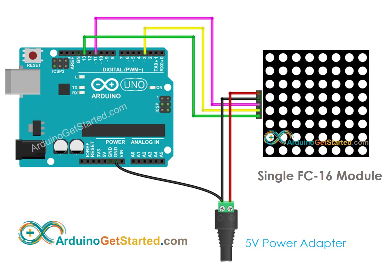
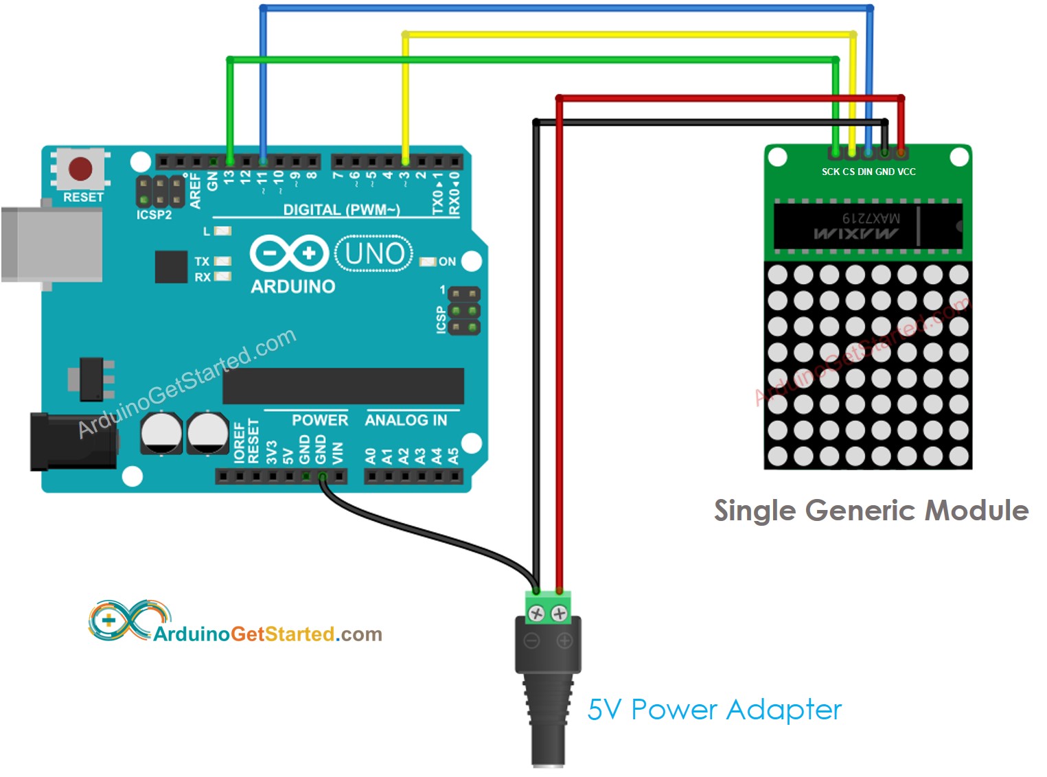
If the LED matrix is made of a single block:
- Connect the input pins groups to Arduino
- Let the output pins group unconnected
This image is created using Fritzing. Click to enlarge image
This image is created using Fritzing. Click to enlarge image
If the LED matrix is pre-built multiple blocks:
- Connect the input pins groups to Arduino
- Let the output pins group unconnected
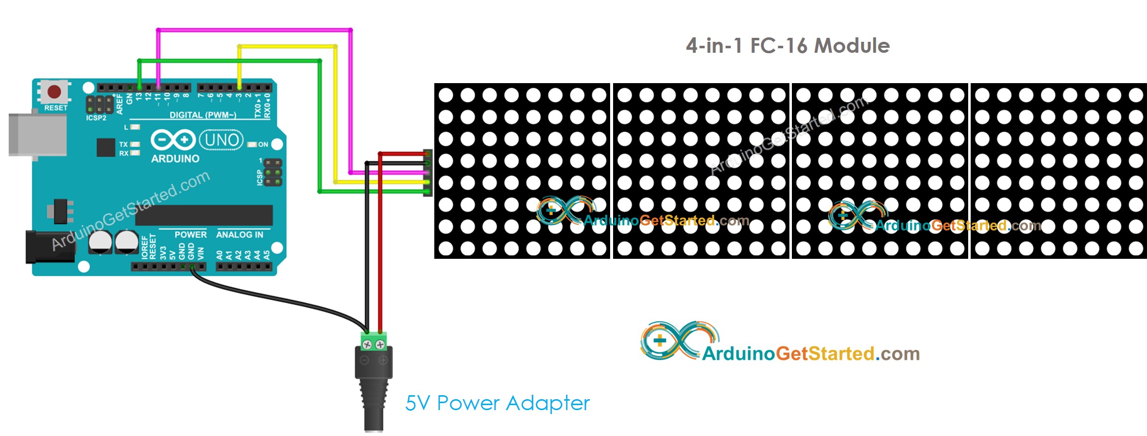
This image is created using Fritzing. Click to enlarge image
If the LED matrix is made of multiple blocks by yourself:
- Connect the input pins groups of the first block to Arduino
- Connect the output pins groups of each block to the input pins groups of the next block
- Let the output pins group of the last block unconnected
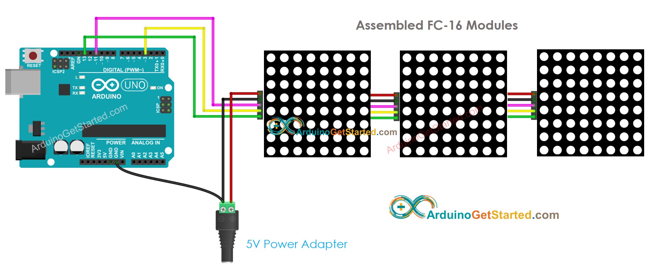
This image is created using Fritzing. Click to enlarge image
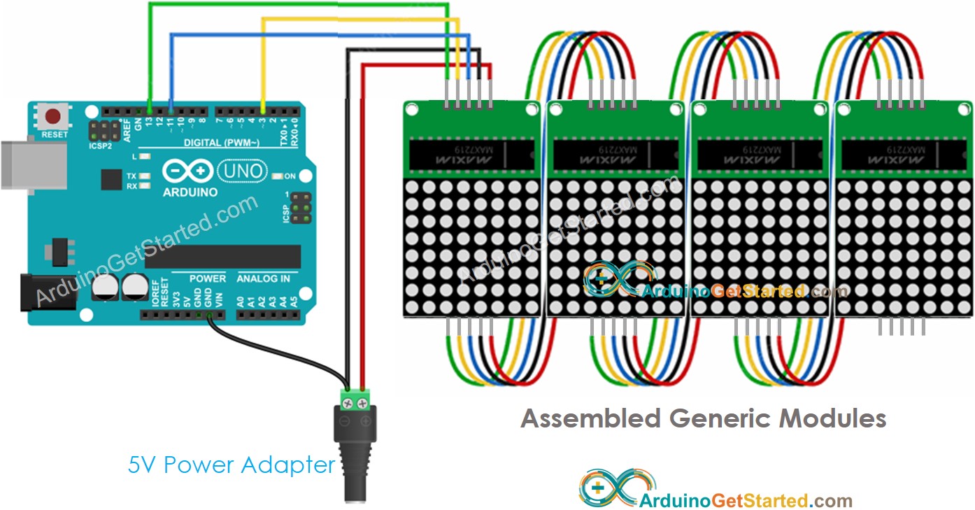
This image is created using Fritzing. Click to enlarge image
Because the display draws a lot of currents (up to 1A at maximum brightness):
- Do not use the power from the 5V pin of Arduino.
- Use an external 5V power supply instead. Arduino and LED matrix can share power from a 5V power adapter
Because Arduino connects to LED matrix via SPI pins:
- Pin 13 (SCK) and 11 (MOSI) on Arduino Uno must be used. If you’re using another Arduino board, check the official documentation for equivalent SPI pins.
- Pin 3 (CS) can be changed to any pin
How To Program For LED Matrix
It is not easy to control the LED matrix. Fortunately, libraries are available to make it easy. Below is a step-by-step on how to write Arduino code to control the LED matrix
- Include libraries:
- Specify which hardware is being used: GENERIC_HW or FC16_HW.
- Define how many LED block is used. for example, a 4-in-1 LED matrix has 4 blocks.
- Define the pin that connects to the LED matrix’s CS pin. For example, pin D3
- Create a new instance of the MD_Parola class for the LED matrix display.
- Code in the setup() function:
- Display text, number and show animated effects: see next part
Arduino - LED Matrix Code
The below code is for 32x8 FC-16 LED matrix display (4 blocks). But you can easily adapt it for 8x8, 16x8, 64x8...
Quick Steps
- Connect Arduino to LED matrix as above wiring diagram
- Connect Arduino to PC via USB cable
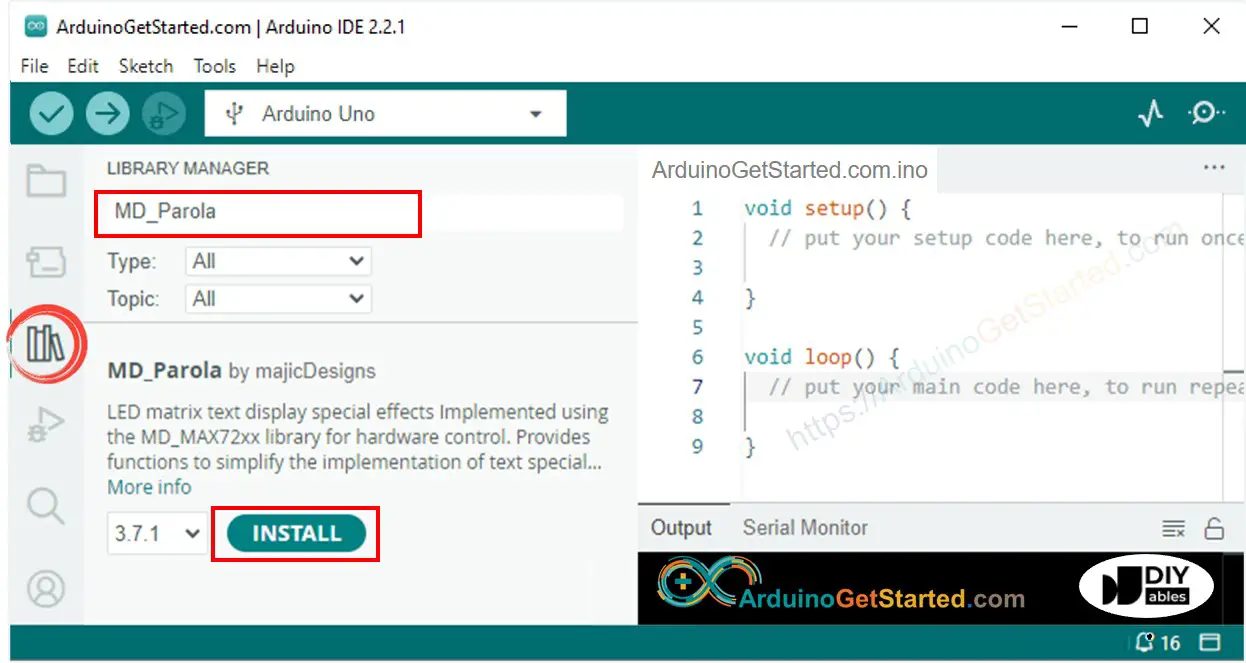
- Navigate to the Libraries icon on the left bar of the Arduino IDE.
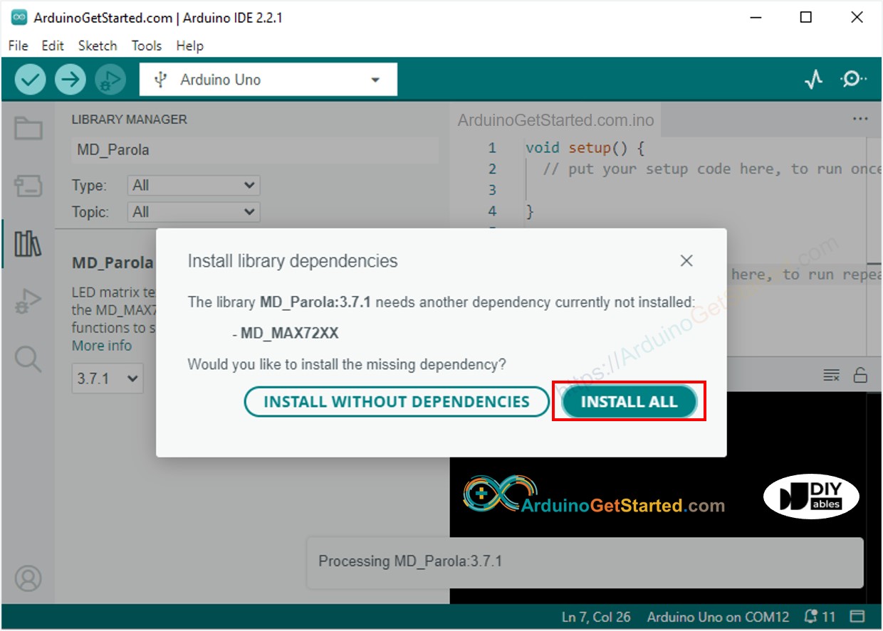
- Search “MD_Parola”, then find the MD_Parola library
- Click Install button.
- You will be asked to install the MD_MAX72XX library for dependency. Click Install All button.
- Copy the above code and open it with Arduino IDE
- Click Upload button on Arduino IDE to upload code to Arduino
- See the LED matrix display
Arduino LED Matrix Code – Scrolling Text
When you want to print a long message that is too long to fit on a LED matrix display, you can use the scroll text effect technique.
The below Arduino code shows how to scroll a message on the LED matrix display.
For more text effects, please visit MD_Parola Library Reference.
Video Tutorial
We are considering to make the video tutorials. If you think the video tutorials are essential, please subscribe to our YouTube channel to give us motivation for making the videos.