Arduino - Water Sensor
The water sensor or water level sensor is used to detect water leakage, rainfall, tank overflow, or to measure the water level. In this tutorial, we will learn:
- How to use the water sensor with Arduino
- How to connect the water sensor to Arduino
- How to program Arduino to read the state from the water sensor
- How to detect the water leakage, rainfall, tank overflow
- How to measure the water level
- How to calibrate the water sensor
Hardware Required
Or you can buy the following kits:
| 1 | × | DIYables STEM V3 Starter Kit (Arduino included) | |
| 1 | × | DIYables Sensor Kit (18 sensors/displays) |
Additionally, some links direct to products from our own brand, DIYables .
About Water Level Sensor
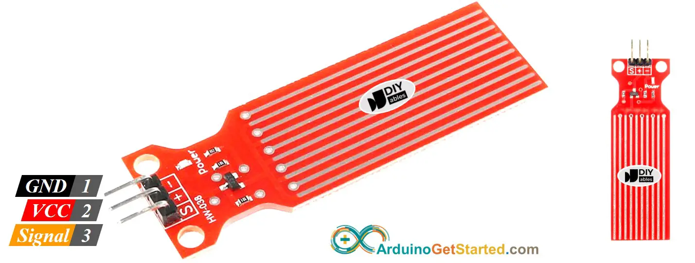
Water Level Sensor Pinout
The water level sensor has 3 pins:
- S (Signal) pin: is an analog output that will be connected to one of the analog inputs on your Arduino.
- + (VCC) pin: supplies power for the sensor. It is recommended to power the sensor with between 3.3V – 5V.
- - (GND) pin: is a ground connection.
※ NOTE THAT:
The analog output value on the signal pin varies depending on the voltage supplied to the VCC pin of the sensor.
How Water Level Sensor Works
Simply, The more water the sensor is immersed in, the higher the output voltage in the signal pin is.
Let's see more deeply.
The sensor has a series of ten exposed copper traces. Five are power traces and five are sense traces. These traces are interlaced in parallel so that there is one sense trace between every two power traces. These traces are not connected unless they are bridged by water when submerged.
The traces act as a variable resistor (just like a potentiometer) whose resistance varies according to the water level.
- The change in resistance corresponds to the distance from the top of the sensor to the surface of the water.
- The resistance is inversely proportional to the height of the water:
- The more water the sensor is immersed in, the better the conductivity is, the lower the resistance is.
- The less water the sensor is immersed in, the worse the conductivity is, the higher the resistance is.
- The sensor produces an output voltage according to the resistance.
By measuring the voltage, we can determine the water level.
Wiring Diagram
In theory, To supply power to the sensor, we can connect the sensor's VCC and GND pins to Arduino's 5v and GND pins, respectively.
In practice, however, that way is not recommended. Because in the moist environment, if we provide power to the sensor constantly, the sensor is electrochemically corroded faster. This shortens the sensor's lifespan. To overcome this issue, we recommend you to do not power the sensor all the time, but power the sensor only when reading the sensor's value. This can be done by connecting the sensor's VCC pin to a digital pin of an Arduino, and set the Arduino's pin to HIGH and LOW before and after reading, respectively.
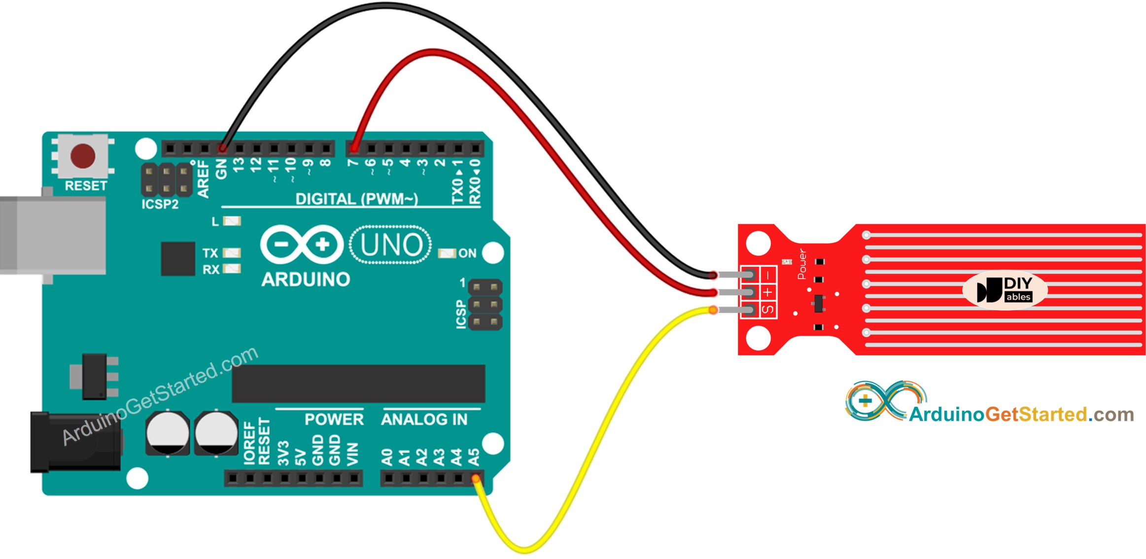
This image is created using Fritzing. Click to enlarge image
Arduino Code - Reading Value from Water Sensor
Quick Steps
- Copy the above code and open with Arduino IDE
- Click Upload button on Arduino IDE to upload code to Arduino
- Slowly dip the sensor into the water ( a glass of water).
- See the result on Serial Monitor. The value 0 when the sensor is not touching anything.
※ NOTE THAT:
The sensor is not designed to be fully submersed, only the exposed traces on the PCB can contact with water. Please be careful to install it.
How To Detect Water Leakage
To detect the water leakage, rainfall, and tank overflow, we just need to compare the reading value with a threshold value. The threshold is determined in the calibration part of this tutorial.
Let's take a specific example. Arduino turns on an LED if the water is detected.
Wiring Diagram
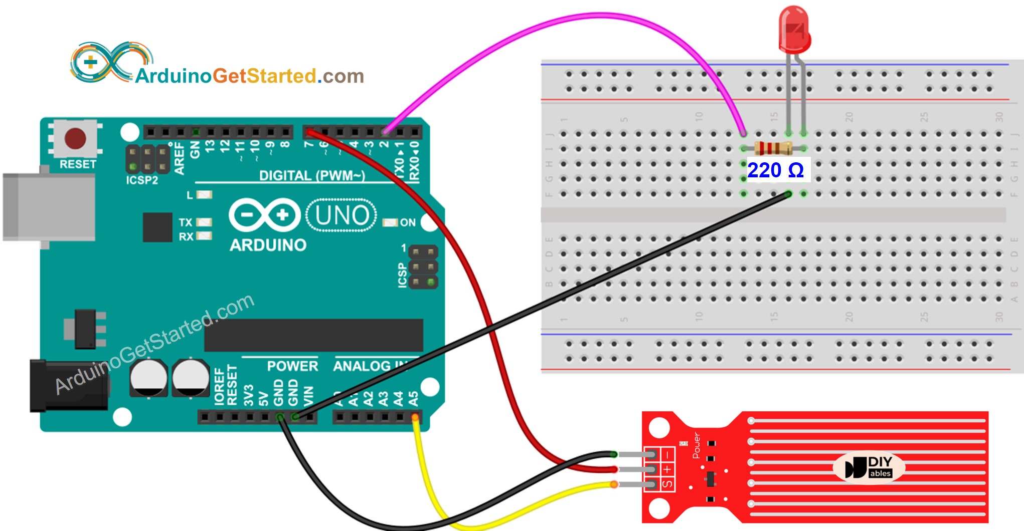
This image is created using Fritzing. Click to enlarge image
Arduino Code - Detecting Water Leakage
How To Measure The Water Level
If you want to divide the maximum height of water into some levels and measure the current level, you can use the method in the below code. Note that the maximum height of the water is equal to the height of the sensor. The below code divides the maximum height into 4 levels.
※ NOTE THAT:
- SENSOR_MIN and SENSOR_MAX is determined by the calibration process.
- The above mapping method is not accurate. However, it is acceptable in many applications. If you want to make it accurate, you can measure the threshold values for each level. See the calibration part
Water Level Sensor Calibration
The output value of the sensor depends on not only the water level but also the water's conductivity. The pure water is not conductive. The water contains minerals and impurities is conductive. The more conductive the water is, the more sensitive the sensor is. On the other hand, the output value also varies depending on the voltage supplied to the VCC pin of the sensor.
To get accurate in reading the water sensor, We recommend you to calibrate the sensor for the particular type of water that you plan to monitor.
Before determining the threshold for triggering an action, you should measure the actual value read from the sensor by doing a test.
How to do the test:
- Use the above sketch for reading sensor value.
- Dip the sensor in the water at the level that you want it to be a threshold.
- Write down the value that the sensor outputs in Serial Monitor.
- Use the value as threshold you intend to trigger an action.
This test may take some trial and error.
The test can also be used to find:
- SENSOR_MIN value, when the sensor is not immersed in the water
- SENSOR_MAX value, when the sensor is fully immersed in the water
- A threshold value for detecting water leakage
- The threshold values for each level of your degree scale.
Video Tutorial
We are considering to make the video tutorials. If you think the video tutorials are essential, please subscribe to our YouTube channel to give us motivation for making the videos.
Challenge Yourself
- Send an email when detecting water leakage
- Send a SMS message when detecting water leakage
- Make a sound alarm when detecting water leakage