Arduino - Actuator with Feedback
In a previous tutorial, we have learned about the linear actuator without feedback. In this tutorial, we are going to learn about the linear actuator with feedback (also called the feedback linear actuator). The feedback from the linear actuator provides the information to identify the position of its stroke, and then control the position. In detail, we are going to learn:
- How a feedback linear actuator works
- How to find the position of the feedback linear actuator (in millimeter)
- How to control the position of a linear actuator
Hardware Required
Or you can buy the following kits:
| 1 | × | DIYables STEM V3 Starter Kit (Arduino included) | |
| 1 | × | DIYables Sensor Kit (18 sensors/displays) |
Additionally, some links direct to products from our own brand, DIYables .
About Feedback Linear Actuator
A feedback linear actuator is a linear actuator that has the feedback signal that allows to identify its position and control it. The feedback is a potentiometer that outputs the voltage value in proportion to the stroke's position.
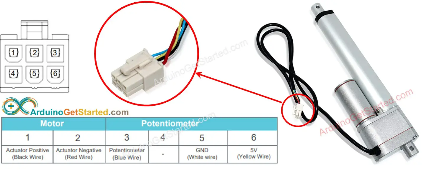
Feedback Linear Actuator Pinout
A Feedback Linear Actuator has 5 wires:
- Actuator Positive wire: This wire is used to control the linear actuator by using high voltage (12V, 24V, 48V...).
- Actuator Positive wire: This wire is used to control the linear actuator by using high voltage (12V, 24V, 48V...).
- 5V wire: this wire is used for the feedback potentiometer. Connect this wire to 5V or 3.3V
- GND wire: this wire is used for the feedback potentiometer. Connect this wire to GND
- Potentiometer wire: (also called feedback wire, or output wire) this wire outputs the voltage value in proportion to the stroke's position.
How It Works
If we provide high voltage to the positive and negative wires, the stroke of the actuator will be extended or retracted. In detail, If we connect:
- 12V (12V, 24V, 48V...) and GND to the positive wire and negative wire, respectively: the linear actuator full-speed extends until it reaches the limit.
- 12V (12V, 24V, 48V...) and GND to the negative wire and positive wire, respectively: the linear actuator full-speed retracts until it reaches the limit.
- While extending or retracting, if we stop power to the actuator (GND to both positive and negative wire), the actuator stops extending/retracting
※ NOTE THAT:
- The voltage value for controlling the actuator depends on the specification of the actuator. Read the datasheet or manual to know the corresponding voltage value.
- The actuator can keep the position even when stopping powering while carrying a load.
The voltage value in the potentiometer wire is proportional to the position of stroke on the actuator. By measuring this voltage, we can know the stroke's position.
Wiring Diagram
Please remove all three jumpers on the L298N module before wiring.
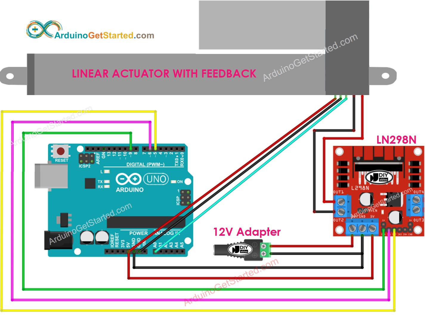
This image is created using Fritzing. Click to enlarge image
How to control extend/retract a linear actuator
See Arduino - Actuator tutorial
How to find the position of the linear actuator
The below shows how to identify the position of stroke on a linear actuator.
Calibration
- Identify the length of the actuator's stroke (in millimeter) by measuring (using a ruler) or reading the datasheet
- Identify the output values when the linear actuator is fully extended and fully retracted by running the below code
- You will see the log on Serial Monitor as below example
- Write down these values
- If the min/max values are swapped, swap IN1_PIN and IN2_PIN
Arduino code that calculate the position of the actuator
- Update the three calibrated values to the code
- Upload the code to Arduino
- See the result on Serial Monitor
How to control a linear actuator to a specific position
Video Tutorial
We are considering to make the video tutorials. If you think the video tutorials are essential, please subscribe to our YouTube channel to give us motivation for making the videos.