Arduino - DC Motor
In this tutorial, we are going to learn:
- How DC motor works
- How to control the speed and direction of DC motor.
- How to control a DC motor using L298N driver.
- How to control two DC motors using L298N driver.
Hardware Required
Or you can buy the following kits:
| 1 | × | DIYables STEM V3 Starter Kit (Arduino included) | |
| 1 | × | DIYables Sensor Kit (18 sensors/displays) |
Additionally, some links direct to products from our own brand, DIYables .
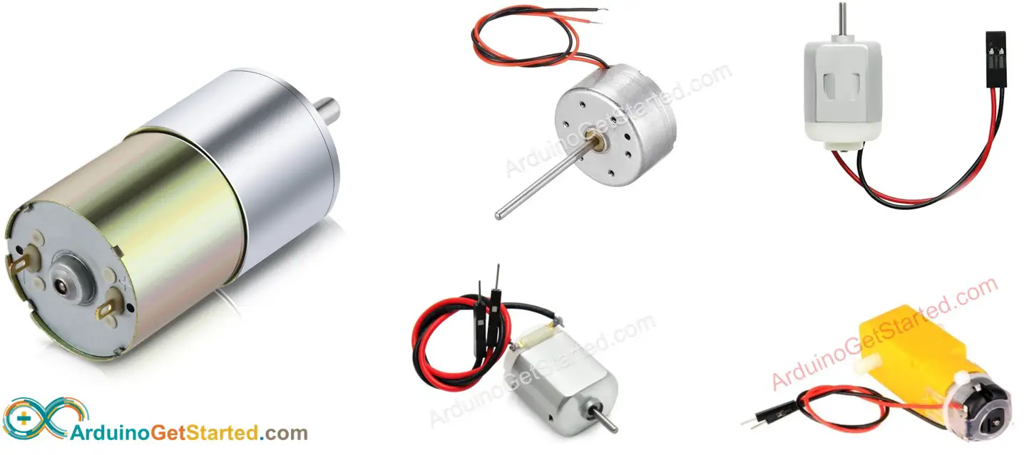
About DC Motor
DC Motor Pinout
DC Motor has two wires:
- Positive wire: usually red
- Negative wire: usually black
How It Works
When you buy a DC motor, you need to know what voltage DC motor work. Let's take a 12V DC motor as an example.
When you power the 12V DC motor by a 12V power source:
- 12V and GND to the positive wire and negative wire, respectively: the DC motor rotates at maximum speed in the clockwise direction
- 12V and GND to the negative wire and positive wire, respectively: the DC motor rotates at maximum speed in the anti-clockwise direction
As described above, when the power pole is swapped between two wires of the DC motor, the rotating direction is reversed. This method is used to control the direction of the DC motor. Of course, not by changing manually but by programming.
If we provide power to DC motors below 12V, the motor still rotates but not at maximum speed. It means if we change the voltage of the power supply, we can change the speed of the DC motor. However, this method is not used in practice because of the difficulty in controlling the voltage of the power source. Instead, we fix the voltage of the power source and control the speed of the DC motor via a PWM signal. The more duty cycle the PWM is, the higher speed the DC motor rotates.
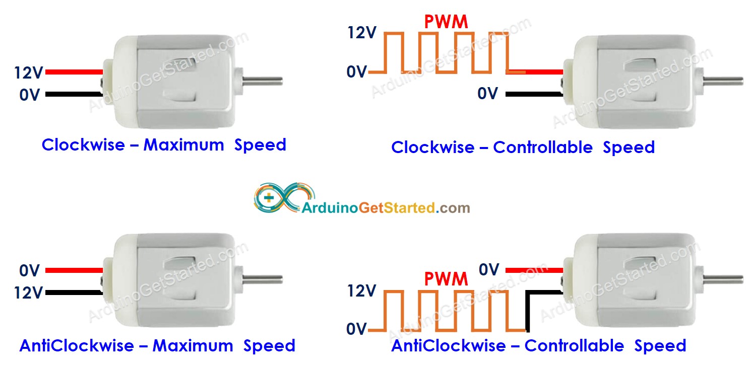
The following animation shows how a PWM signal is used to control the speed of a DC motor:
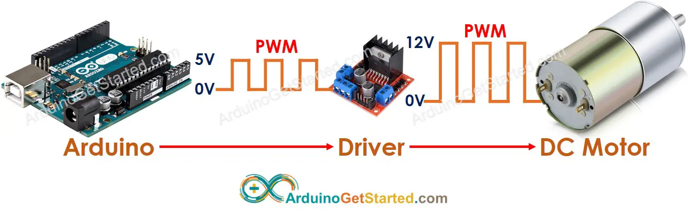
How to control DC motor using Arduino
Controlling DC motor includes two factors: speed and direction. Arduino can generate the PWM signal. However, this PWM signal has low voltage and current, We cannot use it to control the DC motor. We need to use a hardware driver in between Arduino and DC motor. The driver does two works:
- Amplify the PWM signal from Arduino (current and voltage) → for speed control
- Receive the control signal from Arduino to swap pole of power supply → for direction control.
※ NOTE THAT:
- This tutorial can be applied to all DC motors. 12V DC motor is just an example.
- When you controls 5V DC motor, although Arduino pin outputs 5V (the same as DC motor voltage), you still needs a driver in between Arduino and DC motor because the Arduino pin does not provide enough the current for DC motor.
There are many kinds of the chip, modules (e.g. L293D, L298N) can be used as DC motor drivers. In this tutorial, we will use the L298N driver.
About L298N Driver
L298N Driver can be used to control DC motor and stepper motor. In this tutorial, we learn how to use it to control the DC motor.

L298N Driver Pinout
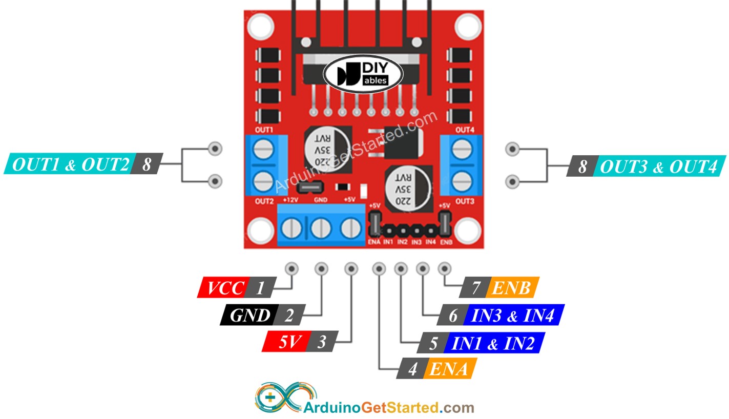
L298N Driver can control two DC motor independently at the same time, called motor A and motor B. L298N Driver has 13 pins:
The common pins for both motors:
- VCC pin: supplies power for the motor. It can be anywhere between 5 to 35V.
- GND pin: is a common ground pin, needs to be connected to GND (0V).
- 5V pin: supplies power for L298N module. It can be supplied by 5V from Arduino.
Motor A pins (Channel A):
- ENA pins: are used to control the speed of Motor A. Removing the jumper and connecting this pin to PWM input will let us control the speed of Motor A.
- IN1 & IN2 pins: are used to control the spinning direction of Motor A. When one of them is HIGH and the other is LOW, the Motor A will spin. If both the inputs are either HIGH or LOW the Motor A will stop.
- OUT1 & OUT2 pins: are connected to Motor A.
Motor B pins (Channel B):
- ENB pins: are used to control the speed of Motor B. Removing the jumper and connecting this pin to PWM input will let us control the speed of Motor B.
- IN3 & IN4 pins: are used to control the spinning direction of Motor B. When one of them is HIGH and the other is LOW, Motor B will spin. If both the inputs are either HIGH or LOW the Motor B will stop.
- OUT3 & OUT4 pins: are connected to Motor B.
As described above, the L298N driver has two input powers:
- One for DC motor (VCC and GND pins): from 5 to 35V.
- One for the L298N module's internal operation (5V and GND pins): from 5 to 7V.
The L298N driver also has three jumpers for advanced uses or other purposes. For the sake of simplicity, please remove all jumpers from the L298N driver.
We can control two DC motors independently at the same time by using an Arduino and an L298N Driver. To control each motor, we need only three pins from Arduino.
※ NOTE THAT:
The rest of this tutorial controls a DC motor using channel A. Controlling the other DC motor is similar.
How To Control the Speed of DC Motor via L298N Driver
It is simple to control the speed of the DC motor by generating a PWM signal to the ENA pin of L298N. We can do this by:
- Connect an Arduino pin to ENA of L298N
- Generate PWM signal to ENA pin by using analogWrite() function. L298N Driver amplify PWM signal to DC motor
The speed is a value between 0 and 255. If the speed is 0, the motor stops. If the speed is 255, the motor spins at maximum speed.
How To Control the Direction of DC Motor via L298N Driver
The spinning direction of a motor can be controlled by applying a logic HIGH/LOW to IN1 and IN2 pins. The below table illustrates how to control the direction in both channels.
| IN1 pin | IN2 pin | Direction |
|---|---|---|
| LOW | LOW | Motor A stops |
| HIGH | HIGH | Motor A stops |
| HIGH | LOW | Motor A spins Clockwise |
| LOW | HIGH | Motor A spins Anti-Clockwise |
- Control motor A spins clockwise
- Control motor A spins anti-clockwise
※ NOTE THAT:
The spinning direction is inverted if the OUT1 & OUT2 pin connects to two pins of the DC motor in an inverse way. If so, it just needs to swap between OUT1 & OUT2 pin or change the control signal on IN1 and IN2 pin in the code.
How To Stop DC Motor Spinning
There are two ways to stop DC motor
- Controls the speed to 0
- Controls IN1 IN2 pins to the same value (LOW or HIGH)
- Or
How to control a DC motor using L298N driver.
Wiring Diagram
Please remove all three jumpers on the L298N module before wiring.
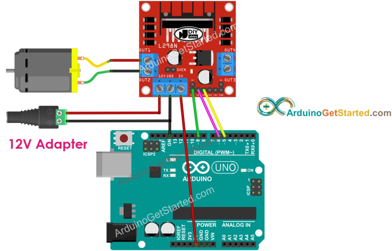
This image is created using Fritzing. Click to enlarge image
Arduino Code
The below code does:
- Speed up DC motor
- Change the direction
- Speed down DC motor
- Stop the motor
Quick Steps
- Remove all three jumpers on the L298N module.
- Copy the above code and open with Arduino IDE
- Click Upload button on Arduino IDE to upload code to Arduino
- You will see:
- DC motor is speeded up and then rotates at the maximum speed 1 second
- DC motor's direction is changed
- DC motor rotates at the maximum speed of 1 second in the reverse direction
- DC motor is speeded down
- DC motor stop 1 second
- The above process is run repeatedly.
※ NOTE THAT:
In this tutorial, we learn how to control the DC motor speed that is relative to the maximum speed. In order to control the absolute speed (round per second), we need to use a PID controller and an encoder. Controlling the absolute speed of the DC motor will be presented in another tutorial.
How to Control two DC Motors using L298N Driver
(comming soon)
Video Tutorial
We are considering to make the video tutorials. If you think the video tutorials are essential, please subscribe to our YouTube channel to give us motivation for making the videos.