Arduino - Measure Voltage
In this tutorial, we will explore how to use an Arduino to measure voltage from 0V to 25V using a voltage sensor. In detail, we will cover:
- How to connect the voltage sensor to Arduino
- How to program Arduino to read voltage from the sensor
Hardware Required
Or you can buy the following kits:
| 1 | × | DIYables STEM V3 Starter Kit (Arduino included) | |
| 1 | × | DIYables Sensor Kit (18 sensors/displays) |
Additionally, some links direct to products from our own brand, DIYables .
About Voltage Sensor
A Voltage Sensor is a pre-assembled voltage divider circuit that employs precision resistors for simplified voltage measurement. It consists of two resistors: 30 KΩ and 7.5 KΩ. With a 5V reference voltage for the ADC, the sensor can measure voltages ranging from 0 to 25V DC. When the ADC's reference voltage is 3.3V, the sensor can measure voltages from 0 to 16.5V DC.
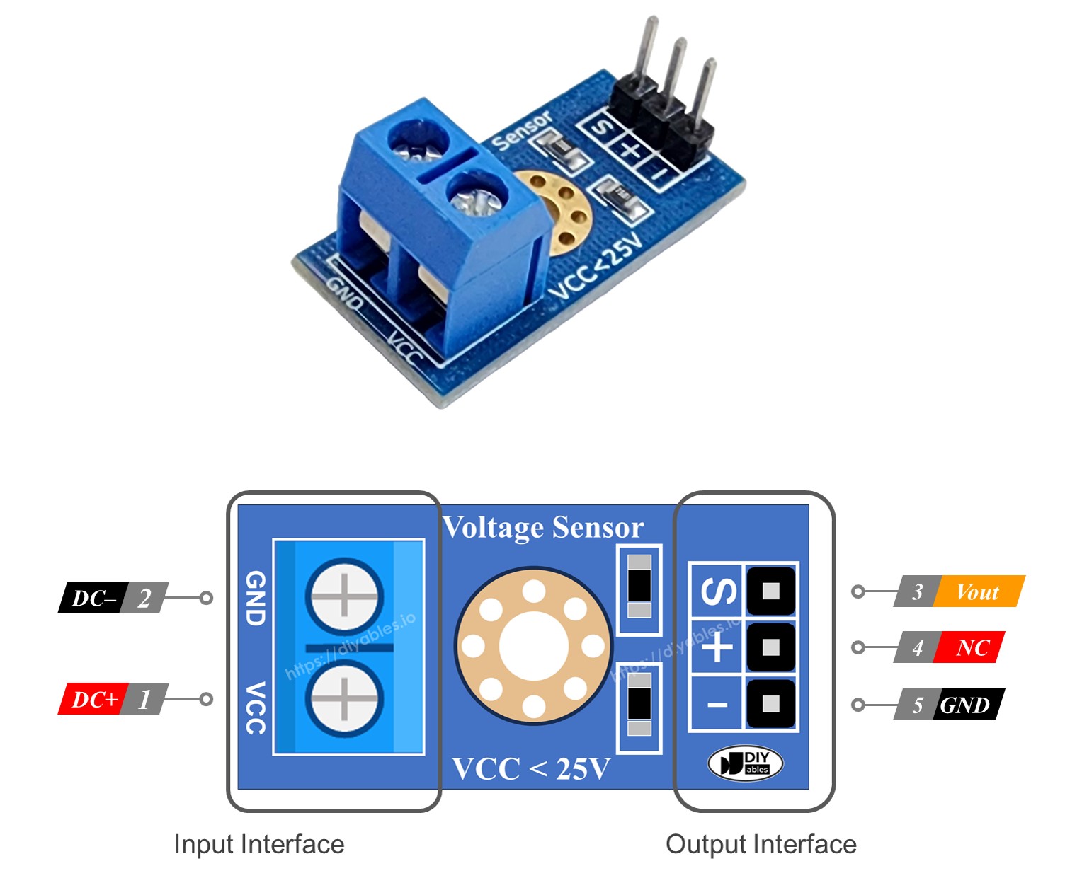
Pinout
A voltage sensor has two sets of pins:
- Input Interface (connected to the points where you want to measure voltage):
- VCC pin: This is the positive pin. Connect it to the point with higher voltage.
- GND pin: This is the negative pin. Connect it to the point with lower voltage.
- Output Interface (connected to the Arduino):
- Vout pin (S): This is the signal pin. Connect it to an analog pin on the Arduino.
- NC pin (+): This is not used. Let it not connected.
- GND pin (-): This is the ground pin. Connect it to the GND (0V) on the Arduino.
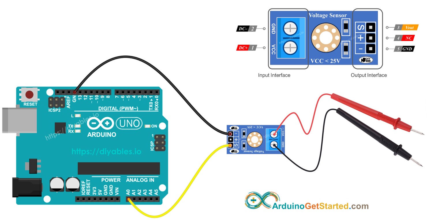
Wiring Diagram

This image is created using Fritzing. Click to enlarge image
Arduino Code
Quick Steps
- Connect Arduino to the voltage sensor
- Connect Arduino to PC via USB cable
- Open Arduino IDE, select the right board and port
- Copy the above code and open with Arduino IDE
- Click Upload button on Arduino IDE to upload code to Arduino
- Testing by measure 5V and 3.3V on Arduino
- See the result on Serial Monitor.
You might notice that the measurement result is incorrect or significantly different from the actual value. Do not blame the voltage sensor module for this. The measured value may show drift because the default voltage reference is 5V, which can be unstable and dependent on the power supply. Here are some solutions to this issue:
- Use a power supply that provides sufficient voltage for the Arduino. You can verify this by using a voltmeter to check if the 5V pin on the Arduino outputs 5V.
- Use an external voltage reference of 3.3V. However, With this method, you can only measure voltages from 0 to 16.5V DC.
Measuring Voltage with a 3.3V Reference
To use this method, you need to set up both the hardware and the code. For the hardware, connect the AREF pin of the Arduino to 3.3V as shown in the diagram below.
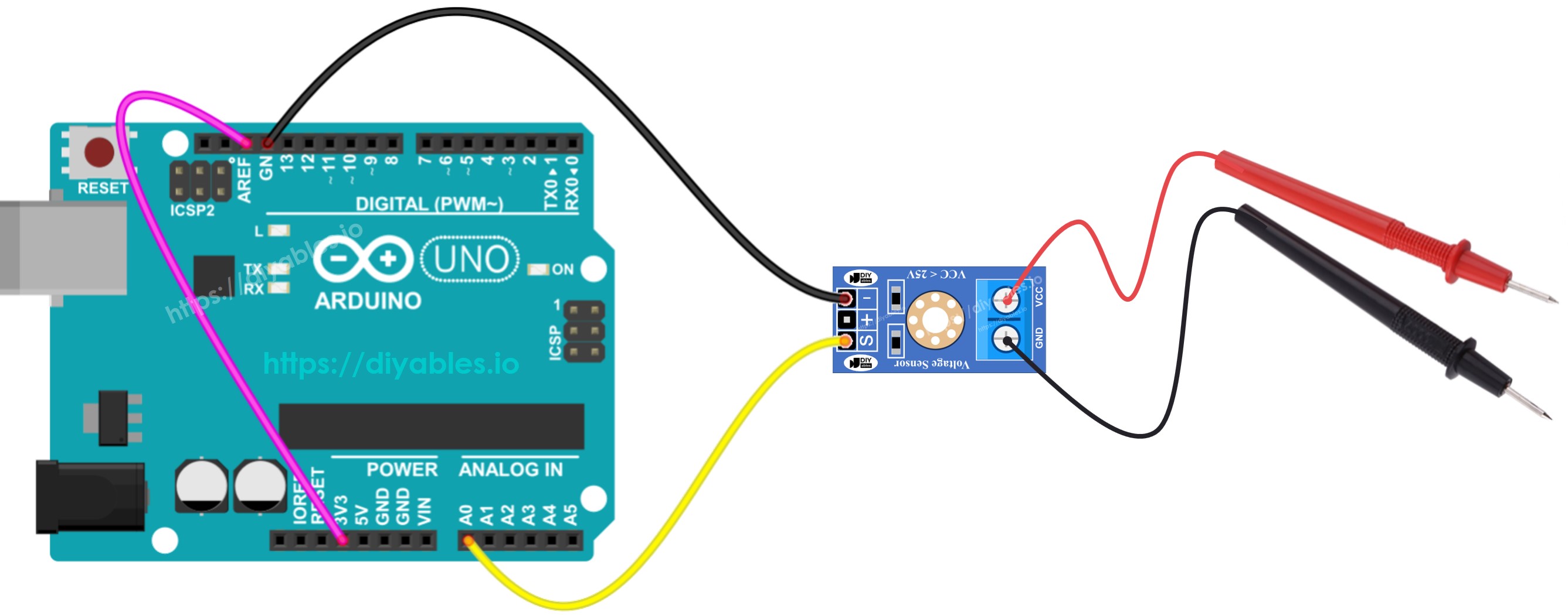
This image is created using Fritzing. Click to enlarge image
Then, use the following code:
Video Tutorial
We are considering to make the video tutorials. If you think the video tutorials are essential, please subscribe to our YouTube channel to give us motivation for making the videos.