Arduino - Light Sensor
In this tutorial, we are going to learn:
- How light sensor works
- How to connect the light sensor to Arduino
- How to program Arduino to read the state from the light sensor
Hardware Required
Or you can buy the following kits:
| 1 | × | DIYables STEM V3 Starter Kit (Arduino included) | |
| 1 | × | DIYables Sensor Kit (18 sensors/displays) |
Additionally, some links direct to products from our own brand, DIYables .
The LDR light sensor is very affordable, but it requires a resistor for wiring, which can make the setup more complex. To simplify the wiring, you can use an LDR light sensor module as an alternative.
About Light Sensor
The light sensor used in this tutorial is a photoresistor, which is also called light-dependent resistor or photocell.
It is used not only to detect light but also to measure the brightness/illuminance level of the ambient light.
Pinout
A photoresistor has two pins. Since it is a kind of resistor, we do NOT need to distinguish these pins. They are symmetric.

How It Works
The more light the photoresistor's face is exposed, the smaller its resistance is. Therefore, by measuring the photoresistor's resistance, we can know how bright the ambient light is.
WARNING
The light sensor value only reflects the approximated trend of the intensity of light, it does NOT represent the exact luminous flux. Therefore, it should be used only in an application that does NOT require high accuracy.
Arduino - Light Sensor
Arduino Uno's pin A0 to A5 can work as the analog input. The analog input pin converts the voltage (between 0v and VCC) into integer values (between 0 and 1023), called ADC value or analog value.
By connecting a pin of the photoresistor to an analog input pin, we can read the analog value from the pin by using analogRead() function, and then we can know the light levels relatively.
Wiring Diagram
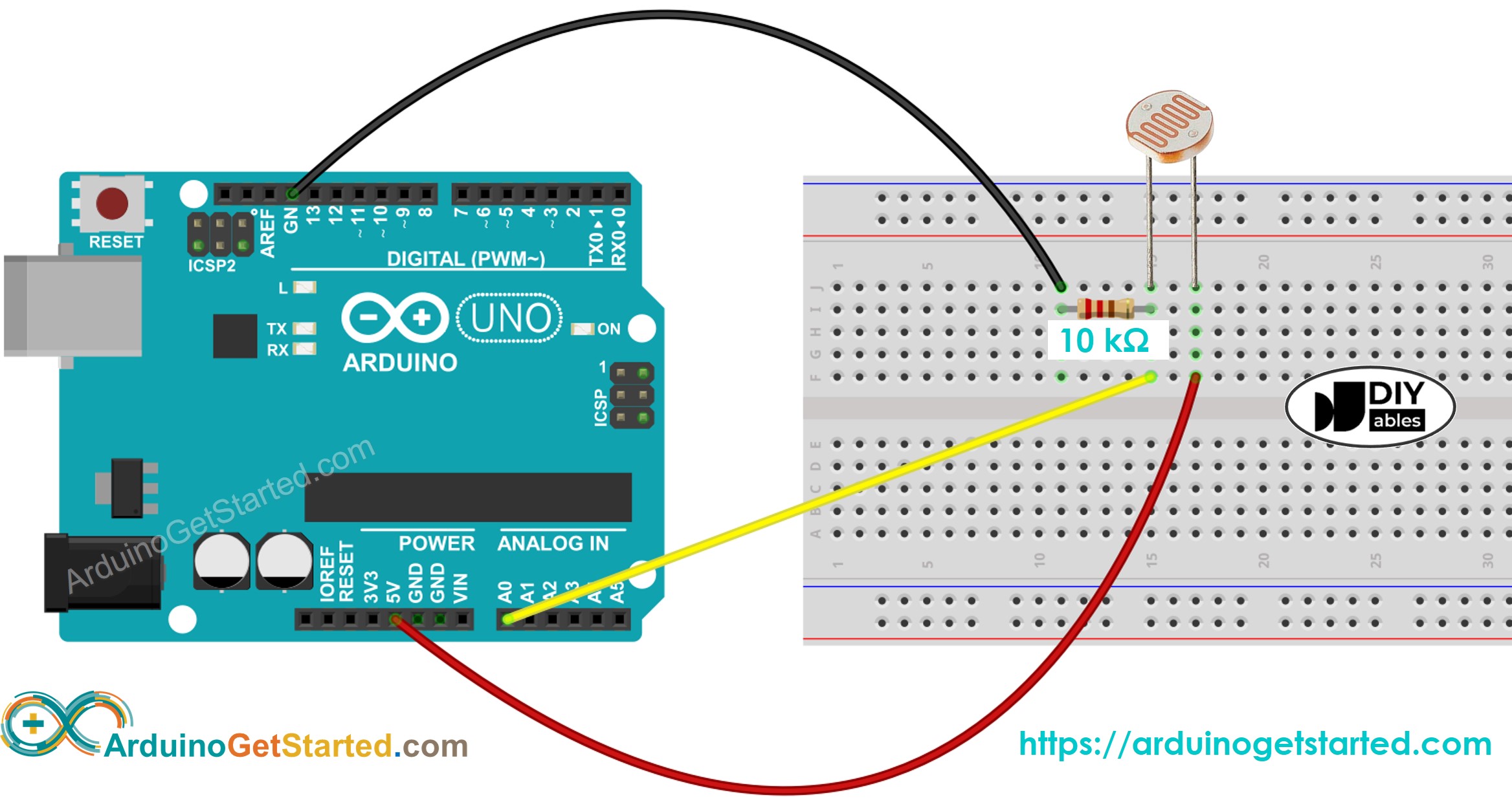
This image is created using Fritzing. Click to enlarge image
Arduino Code
The below code reads the value from photocell and determine the light level qualitatively
Quick Steps
- Copy the above code and open with Arduino IDE
- Click Upload button on Arduino IDE to upload code to Arduino
- Open Serial Monitor
- Radiates light to sensor
- See the result on Serial Monitor:
Light Sensor and LED
- The below code turns ON the LED when it is dark, otherwise turns OFF the LED
- Wring diagram for the above code:
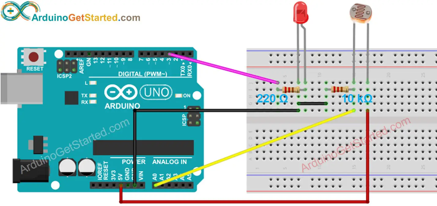
This image is created using Fritzing. Click to enlarge image
Video Tutorial
We are considering to make the video tutorials. If you think the video tutorials are essential, please subscribe to our YouTube channel to give us motivation for making the videos.
Challenge Yourself
- Automatically turn on the light when your room is dark. Hint: Refer to Arduino - Relay.