Arduino - DRV8825 Stepper Motor Driver
In this tutorial, we are going to learn about DRV8825 Stepper Motor Driver and how to use it with Arduino to control the stepper motor. In detail, we will learn:
- What is the DRV8825 stepper motor driver module
- How the DRV8825 stepper motor driver module works
- How to connect the DRV8825 stepper motor driver to Arduino and stepper motor
- How to program Arduino to control stepper motor via DRV8825 module

Hardware Required
Or you can buy the following kits:
| 1 | × | DIYables STEM V3 Starter Kit (Arduino included) | |
| 1 | × | DIYables Sensor Kit (30 sensors/displays) | |
| 1 | × | DIYables Sensor Kit (18 sensors/displays) |
Additionally, some links direct to products from our own brand, DIYables .
About DRV8825 Stepper Motor Driver
The DRV8825 is a stepper motor driver module widely used for controlling bipolar stepper motors in applications like CNC machines, 3D printers, and robotics. It features an adjustable current limit, over-temperature protection, and six-step microstepping options, including full-step, 1/2, 1/4, 1/8, 1/16, and 1/32. The module can handle up to 2.2A per coil with proper cooling and operates at a wide voltage range of 8.2V to 45V, making it suitable for a variety of stepper motors.
To learn about stepper motor's concept like: full-step, microstepping, unipolar stepper, and bipolar stepper, refer to Arduino - Stepper Motor tutorial
It's impressive that controlling the speed and direction of a bipolar stepper motor, such as the NEMA 17, requires just two pins of Arduino.
DRV8825 Stepper Motor Driver Pinout

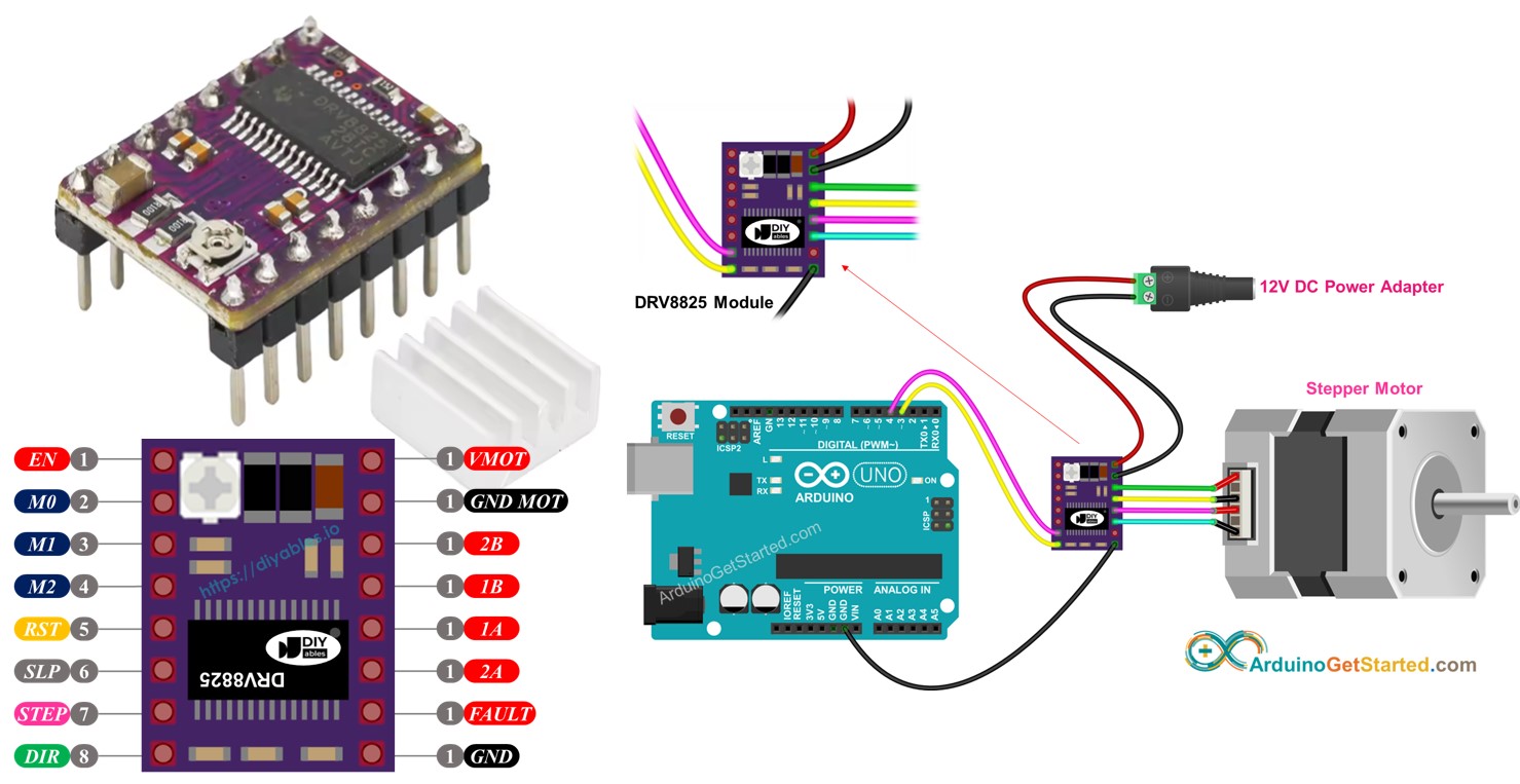
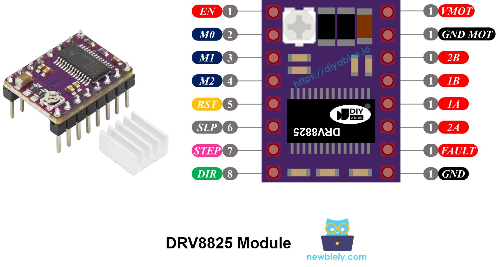
The DRV8825 Stepper motor driver has 16 pins. Below is a typical pinout for the DRV8825 stepper motor driver module. Note that some module variations may label pins slightly differently, but the functionality remains the same.
| Pin Name | Description |
|---|---|
| VMOT | Motor power supply (8.2 V to 45 V). This powers the stepper motor. |
| GND (for Motor) | Ground reference for the motor power supply. Connect this pin to the GND of the motor power supply |
| 2B, 2A | Outputs to Coil B of the stepper motor. |
| 1A, 1B | Outputs to Coil A of the stepper motor. |
| FAULT | Fault Detection Pin. This is an output pin that drives LOW whenever the H-bridge FETs are disabled as the result of over-current protection or thermal shutdown. |
| GND (for Logic) | Ground reference for the logic signals. Connect this pin to the GND of Arduino |
| ENABLE | Active-Low pin to enable/disable the motor outputs. LOW = Enabled, HIGH = Disabled. |
| M1, M2, M3 | Microstepping resolution selector pins (see table below). |
| RESET | Active-Low reset pin - pulling this pin LOW resets the driver. |
| SLEEP | Active-Low sleep pin - pulling this pin LOW puts the driver into low-power sleep mode. |
| STEP | Step input - a rising edge on this pin advances the motor by one step (or one microstep, depending on microstepping setting). |
| DIR | Direction input - sets the rotation direction of the stepper motor. |
Additionally, there is a small on-board potentiometer that you can adjust to set the current limiting, helping to prevent the stepper motor and driver from overheating.
In summary, these 16 pins are organized into the following categories based on their functionality:
- Pins connected to the stepper motor: 1A, 1B, 2A, 2B.
- Pins connected to Arduino for driver control: ENABLE, M1, M2, M3, RESET, SLEEP.
- Pins connected to Arduino for motor direction and speed control: DIR, STEP.
- Pin for feedback to Arduino: FAULT.
- Pins connected to the motor power supply: VMOT, GND (motor power ground).
- Pin connected to the Arduino ground: GND (logic ground).
The DRV8825 module does not require a logic supply from the Arduino board, as it draws power from the motor power supply using its internal 3.3V voltage regulator. However, it is essential to connect the Arduino's ground to the GND (logic) pin of the DRV8825 module to ensure proper operation and a shared ground reference.
Microstep Configuration
The DRV8825 driver enables microstepping by dividing each step into smaller increments. This is achieved by applying intermediate current levels to the motor coils.
For example, NEMA 17 motor with a 1.8° step angle (200 steps per revolution):
- Full-step (1/1) mode: 200 steps per revolution
- 1/2-step mode: 400 steps per revolution
- 1/4-step mode: 800 steps per revolution
- 1/8-step mode: 1600 steps per revolution
- 1/16-step mode: 3200 steps per revolution
- 1/32-step mode: 6400 steps per revolution
As you increase the microstepping level, the motor moves more smoothly and precisely, but at the cost of additional steps required per revolution. If you continue using the same step pulse rate (pulses per second), then each revolution will take longer, effectively slowing down the motor.
However, if your microcontroller can output pulses quickly enough to match the higher step count, you can maintain or even increase speed. The practical limit depends on how rapidly both the driver and your microcontroller can process these pulses without losing steps.
DRV8825 Microstep Selection Pins
The DRV8825 features three microstep resolution selector inputs: M0, M1, and M2 pins. By configuring these pins with specific logic levels, you can choose from six microstepping resolutions:
| M0 Pin | M1 Pi | M2 Pi | Microstep Resolution |
|---|---|---|---|
| Low | Low | Low | Full step |
| High | Low | Low | Half step |
| Low | High | Low | 1/4 step |
| High | High | Low | 1/8 step |
| Low | Low | High | 1/16 step |
| High | Low | High | 1/32 step |
| Low | High | High | 1/32 step |
| High | High | High | 1/32 step |
These microstep selection pins are equipped with on-board pull-down resistors that keep them in a LOW state by default. If left unconnected, the motor will operate in full-step mode.
How it Works
To control a stepper motor using the DRV8825 module, you need at least two Arduino pins: one for the DIR pin and one for the STEP pin. The DRV8825 interprets these signals from the Arduino to move the stepper motor precisely.
- STEP Pin: Each pulse on the STEP pin advances the motor by one microstep (or a full step, depending on your microstepping configuration).
- DIR Pin: Determines the rotation direction of the motor.
The driver then uses these signals, along with its own settings, to send control outputs to the motor through the 1A, 1B, 2A, and 2B pins.
You can also configure additional pins on the DRV8825 module (ENABLE, M1, M2, M3, RESET, SLEEP) in one of three ways:
- Leave them unconnected to allow the driver to operate with default settings.
- Hard-wire them to GND or VCC for a fixed operating mode.
- Connect them to Arduino pins so you can control these features dynamically in your code.
Wiring Diagram between Arduino, DRV8825 module and Stepper Motor
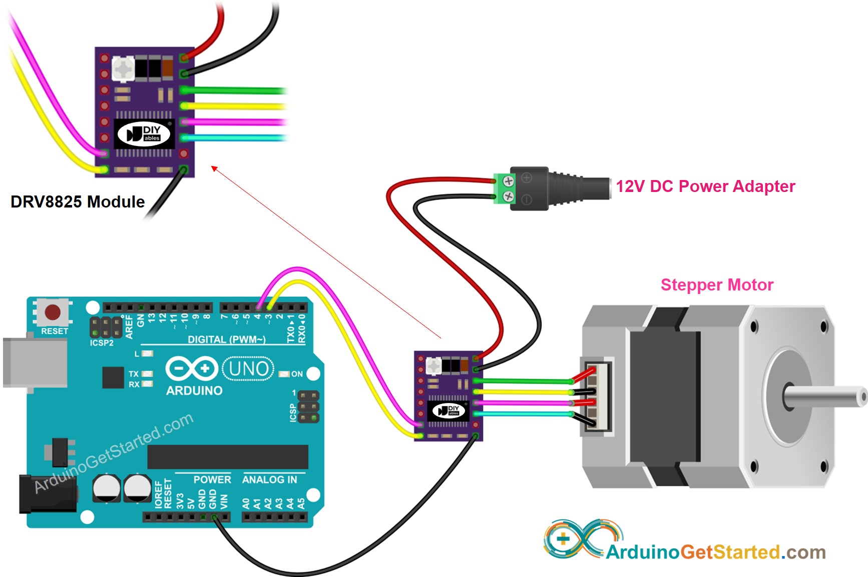
The following wiring diagram shows the minimal connections needed between the Arduino, DRV8825 module, and the stepper motor. With this setup, the DRV8825 driver operates in its default mode (full-step).

This image is created using Fritzing. Click to enlarge image
In detail:
- VMOT: Connect to the motor power supply (e.g., 12V).
- GND (for Motor): Connect to the ground of the motor power supply.
- 1A, 1B, 2A, 2B: Connect to the stepper motor coils.
- STEP: Connect to Arduino digital pin D4.
- DIR: Connect to Arduino digital pin D3.
- GND (for Logic): Connect to Arduino GND pin.
- Other pins: left unconnected.
Arduino Code
Quick Steps
- Copy the above code and open with Arduino IDE
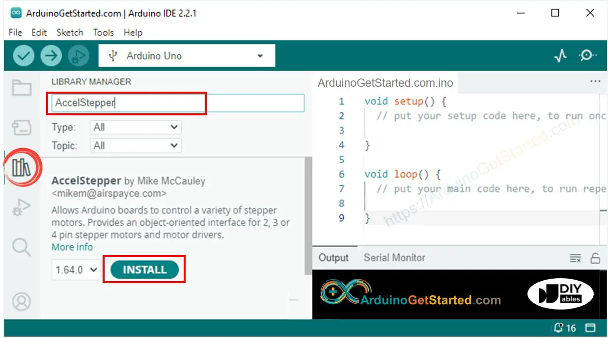
- Navigate to the Libraries icon on the left bar of the Arduino IDE.
- Search “AccelStepper”, then find the AccelStepper library by Mike McCauley
- Click Install button to install AccelStepper library.

- Copy the above code and open with Arduino IDE
- Click Upload button on Arduino IDE to upload code to Arduino
- You will see the motor rotate back and ford
Note: When operating the motor in full-step mode, its motion may not be very smooth, which is normal. For smoother motion, enable microstepping by configuring the M1, M2, and M3 pins.
Video Tutorial
We are considering to make the video tutorials. If you think the video tutorials are essential, please subscribe to our YouTube channel to give us motivation for making the videos.
