Arduino - Multi-Function Shield
This tutorial instructs you how to use Arduino with the Multi-Function Shield. In detail, we will learn:
- How to connect the Multi-Function Shield to Arduino.
- How to program Arduino to display numbers and text on the 4-digit 7-segment display.
- How to program Arduino to detect button presses.
- How to program Arduino to control LEDs (turn on, turn off, blink).
- How to program Arduino to beep the buzzer.
- How to program Arduino to read the potentiometer value.
- How to program Arduino to read the temperature from the LM35 sensor.
Watch this step-by-step video tutorial demonstrating all examples of the Multi-Function Shield. Note that the video shows Arduino Uno R4, but it works identically for Arduino Uno R3:
Hardware Required
Or you can buy the following kits:
| 1 | × | DIYables STEM V3 Starter Kit (Arduino included) | |
| 1 | × | DIYables Sensor Kit (18 sensors/displays) |
Additionally, some links direct to products from our own brand, DIYables .
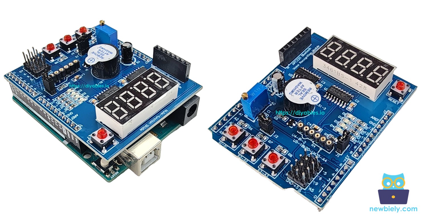
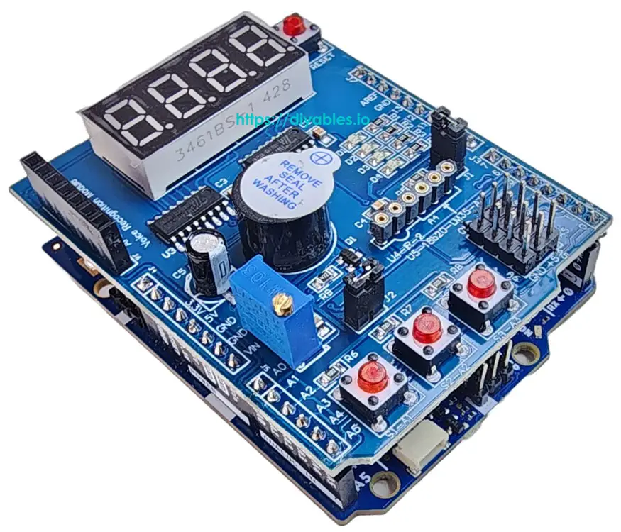
About Multi-Function Shield
The Multi-Function Shield is an all-in-one learning and prototyping shield designed for Arduino Uno and Mega boards. It integrates several common components onto a single board, eliminating the need for complex wiring.
The shield includes the following components:
- 4-Digit 7-Segment Display: Driven by a 74HC595 shift register. Displays numbers, text (A–Z), and special characters like the degree symbol (°).
- 3 Push Buttons (S1, S2, S3): Active LOW with internal pullup resistors. Useful for user input and menu navigation.
- 4 LEDs (D1, D2, D3, D4): Active LOW. Can be turned on, off, toggled, or blinked independently or all together.
- Buzzer: Active LOW. Can produce beeps of configurable duration with optional delay.
- Potentiometer: Connected to analog pin A0. Reads a value from 0 to 1023 (or percentage 0–100%).
- LM35 Temperature Sensor: Connected to analog pin A4. Reads temperature in Celsius. Requires jumper J1 to be removed.
For boards based on the Arduino Uno form factor (such as the Arduino Uno or Mega), the Multi-Function Shield stacks directly onto the board, making it a true plug-and-play solution — no breadboard or jumper wires needed. For boards with Uno form factor but different pin naming (such as the DIYables ESP32-S3 Uno), the library supports custom pin mapping.
Pin Mapping
| Function | Arduino Pin | Function | Arduino Pin |
|---|---|---|---|
| LED D1 | 13 | Button S1 | A1 |
| LED D2 | 12 | Button S2 | A2 |
| LED D3 | 11 | Button S3 | A3 |
| LED D4 | 10 | Potentiometer | A0 |
| Buzzer | 3 | LM35 Temp Sensor | A4 |
| Display LATCH | 4 | ||
| Display CLOCK | 7 | ||
| Display DATA | 8 |
Wiring Diagram
Connecting the Arduino to the Multi-Function Shield is straightforward. Simply stack the Multi-Function Shield onto the Arduino, ensuring proper alignment with the header pins, as illustrated in the image below.
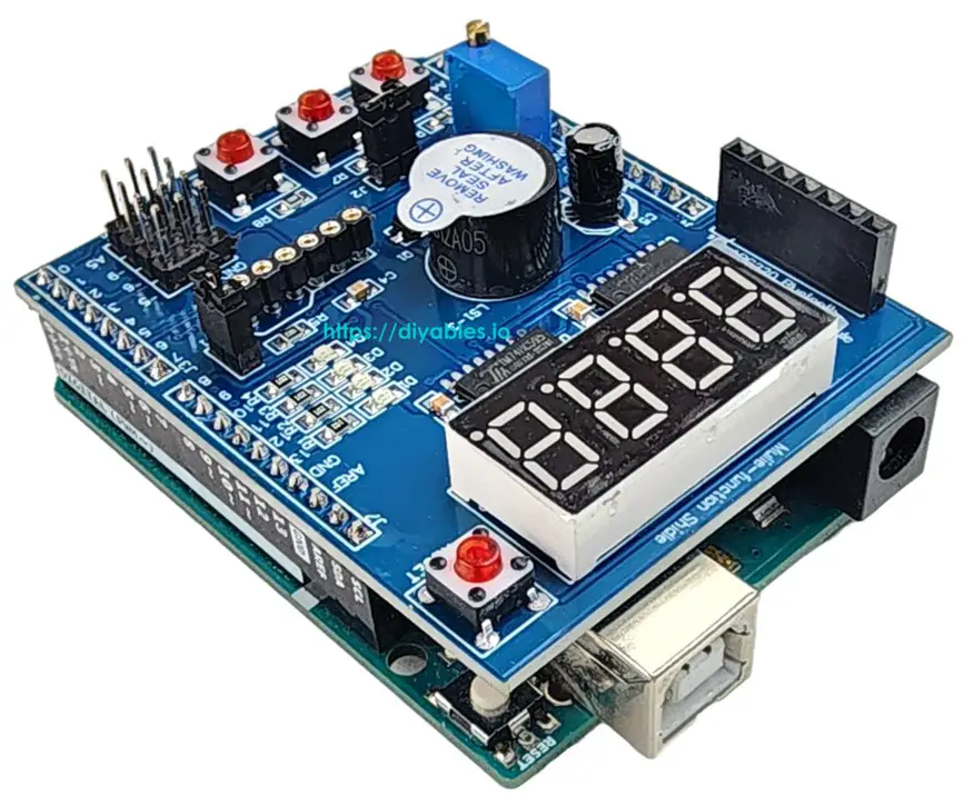
This image is created using Fritzing. Click to enlarge image
Library Installation
- Connect the Arduino board to your computer with a USB cable.
- Open Arduino IDE, select the right board and port.
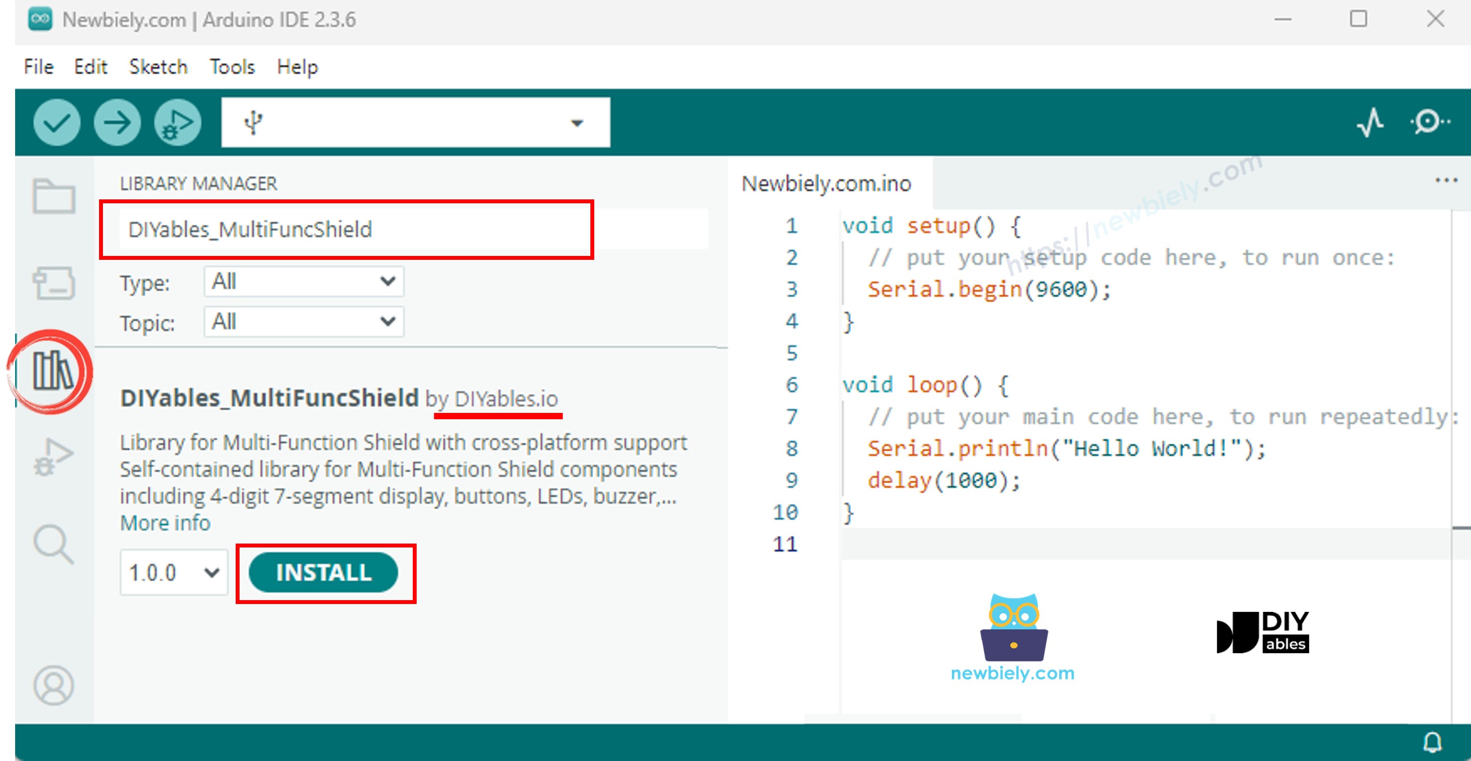
- Navigate to the Libraries icon on the left bar of the Arduino IDE.
- Search "DIYables_MultiFuncShield", then find the DIYables_MultiFuncShield library by DIYables.
- Click Install button to install the latest version of the library.
Note: This library is self-contained with no external dependencies.
Basic Structure
Every sketch using the Multi-Function Shield follows this basic structure:
MFS.begin() initializes all components (display, buttons, LEDs, buzzer). MFS.loop() updates display multiplexing, button debouncing, LED blinking, and buzzer timing. Both calls are required.
Arduino Code - 7-Segment Display
The following code demonstrates how to display integers, floats, text, and special characters on the 4-digit 7-segment display.
Quick Steps
- Stack the Multi-Function Shield on the Arduino board.
- Connect the Arduino board to your computer with a USB cable.
- Open Arduino IDE, select the right board and port.
- Copy the above code and paste it to the editor of Arduino IDE.
- Click Upload button on Arduino IDE to upload code to Arduino.
The display cycles through 7 modes every 3 seconds: integer, leading zeros, float, text, text with dot, degree symbol, and dashes.
Display API Summary
| Method | Description | Example | ||
|---|---|---|---|---|
| print(int) | Display integer | MFS.display.print(42) | ||
| print(int, true) | Integer with leading zeros | MFS.display.print(42, true) → 0042 | ||
| print(float, dp) | Float with decimal places | MFS.display.print(3.14, 2) | ||
| print(text) | Display text (A-Z, 0-9, -, _) | MFS.display.print("HELP") | ||
| setNumber(pos, val) | Set single digit (pos 1-4) | MFS.display.setNumber(1, 5) | ||
| setChar(pos, ch) | Set character at position | MFS.display.setChar(2, 'A') | ||
| setChar(pos, SegChars) | Set special character | MFS.display.setChar(3, SegChars | DEGREE) | |
| setDot(pos) | Add dot at position | MFS.display.setDot(2) | ||
| clear() | Clear all digits and dots | MFS.display.clear() | ||
| show() | Commit manual changes | MFS.display.show() |
Note: The print() methods call show() automatically. Use clear(), setNumber(), setChar(), setDot(), then show() for manual control.
Available special characters via SegChars: DASH (-), UNDERSCORE (_), C, E, F, DEGREE (°).
Arduino Code - LEDs
The following code turns on LEDs one by one, then blinks them all together.
Quick Steps
- Copy the above code and paste it to the editor of Arduino IDE.
- Click Upload button on Arduino IDE to upload code to Arduino.
The LEDs light up sequentially with a 500 ms delay, then all 4 LEDs blink together.
LED API Summary
| Method | Description |
|---|---|
| turnON() | Turn LED on |
| turnOFF() | Turn LED off |
| toggle() | Toggle LED state |
| blink(interval) | Blink with equal on/off time |
| blink(onTime, offTime) | Blink with separate on/off times |
| isOn() | Returns true if LED is currently on |
Convenience methods on MFS:
| Method | Description |
|---|---|
| allLedsOn() | Turn on all 4 LEDs |
| allLedsOff() | Turn off all 4 LEDs |
| allLedsBlink(interval) | Blink all LEDs together |
| allLedsBlink(onTime, offTime) | Blink all with separate on/off times |
LEDs are active LOW. Access by name (MFS.led1 to MFS.led4) or by index (MFS.led(1) to MFS.led(4)).
Arduino Code - Buzzer
The following code beeps the buzzer every 2 seconds.
Quick Steps
- Copy the above code and paste it to the editor of Arduino IDE.
- Click Upload button on Arduino IDE to upload code to Arduino.
You will hear a short beep every 2 seconds.
Buzzer API Summary
| Method | Description |
|---|---|
| beep(ms) | Beep for the specified duration |
| beep(ms, delayMs) | Wait delayMs, then beep for ms |
| stop() | Stop the buzzer immediately |
| isBeeping() | Returns true if buzzer is currently on |
Arduino Code - Potentiometer
The following code reads the potentiometer and prints the value and percentage to the Serial Monitor.
Quick Steps
- Copy the above code and paste it to the editor of Arduino IDE.
- Click Upload button on Arduino IDE to upload code to Arduino.
- Open the Serial Monitor.
- Turn the potentiometer knob and observe the value change on the Serial Monitor.
Potentiometer API Summary
| Method | Returns | Description |
|---|---|---|
| readPot() | int | Raw ADC value (0–1023 on Uno) |
| readPotPercent() | float | Percentage (0.0 – 100.0) |
Arduino Code - Temperature Sensor (LM35)
The following code reads the LM35 temperature sensor and shows the Celsius value on the display and Serial Monitor.
Important: You must remove jumper J1 on the shield to use the LM35 temperature sensor (pin A4 is shared with I2C SDA).
Quick Steps
- Remove jumper J1 on the Multi-Function Shield.
- Copy the above code and paste it to the editor of Arduino IDE.
- Click Upload button on Arduino IDE to upload code to Arduino.
- Open the Serial Monitor.
- Observe the temperature reading on the display and Serial Monitor.
The temperature reading uses a 4-sample moving average for stable values. The buffer is automatically primed on the first read to avoid cold-start errors.
Arduino Multi-Function Shield - Full Demo
The below is a step-by-step video tutorial demonstrating all examples of the Multi-Function Shield. Note that the video shows Arduino Uno R4, but it works identically for Arduino Uno R3:
Platform Support
The library supports all Arduino platforms (architectures=*).