Arduino - DC Motor Shield
This tutorial instructs you how to control a DC motor using Arduino with the Motor Shield Rev3. In detail, we will learn:
- How to mount the Motor Shield Rev3 onto the Arduino.
- How to connect a DC motor and an external power source.
- How to program Arduino to control the motor direction (forward/backward).
- How to program Arduino to control the motor speed using PWM.
- How to program Arduino to activate and release the brake.
- How to program Arduino to read the motor current.
- How to control two DC motors simultaneously using both channels.
Hardware Required
Or you can buy the following kits:
| 1 | × | DIYables STEM V3 Starter Kit (Arduino included) | |
| 1 | × | DIYables Sensor Kit (18 sensors/displays) |
Additionally, some links direct to products from our own brand, DIYables .
About Motor Shield Rev3
The Arduino Motor Shield Rev3 is based on the L298P dual full-bridge driver IC, which allows you to drive two DC motors (or one stepper motor) with full control over direction, speed, and braking.
The shield provides the following features:
- Two motor channels (A and B): Each channel can independently drive one DC motor.
- Direction control: Set the motor to spin forward or backward using a digital pin.
- PWM speed control: Adjust the motor speed from 0 to 255 using a PWM pin.
- Brake control: Engage or release the brake on each channel using a digital pin.
- Current sensing: Read the current drawn by each motor via analog pins.
The Motor Shield Rev3 is designed for the Arduino Uno form factor and stacks directly on top of the Arduino board - no breadboard or complex wiring needed.
Pin Mapping
| Function | Channel A | Channel B |
|---|---|---|
| Direction | D12 | D13 |
| PWM (Speed) | D3 | D11 |
| Brake | D9 | D8 |
| Current Sensing | A0 | A1 |
External Power
The Motor Shield Rev3 requires an external power source for the motors. Connect your power source (6-12V) to the power screw terminals on the shield. The power from the external source drives the motors, while the Arduino can be powered separately via USB or its own power supply.
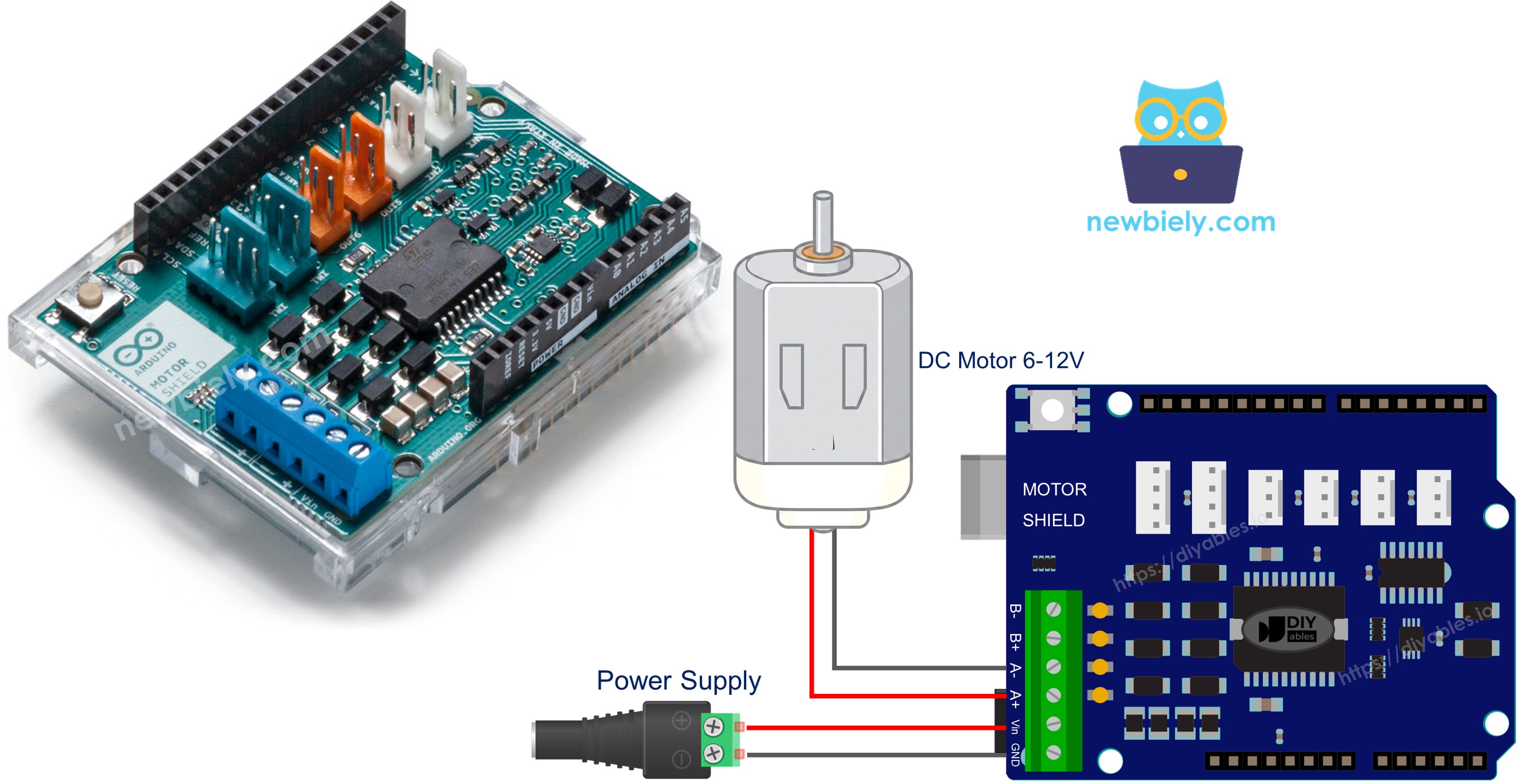
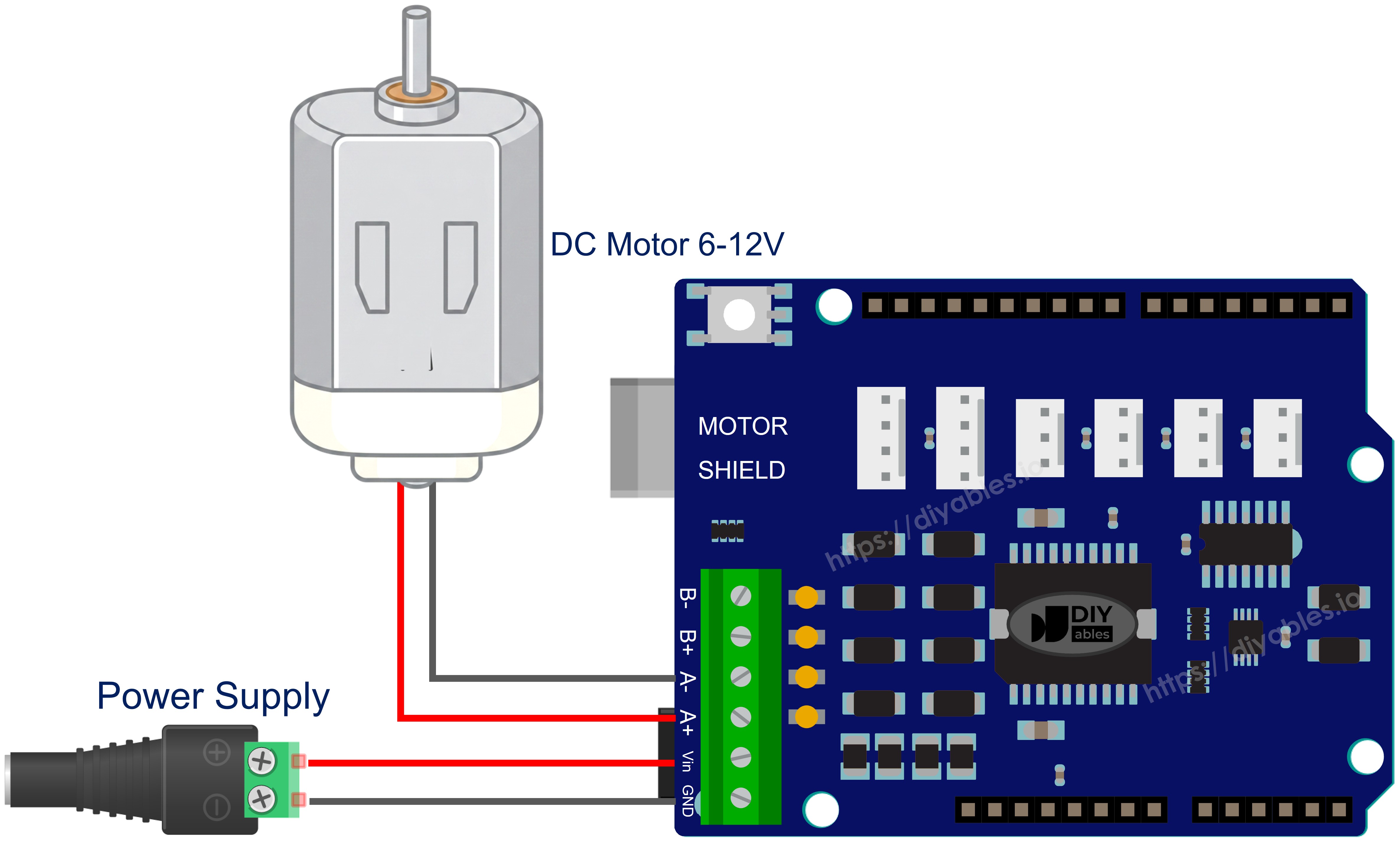
Wiring Diagram
First, mount the Arduino Motor Shield Rev3 on top of the Arduino Uno, aligning the pins carefully.
Then, connect the DC motor to Channel A using the screw terminals on the shield. The channels are marked next to the screw terminals.
Finally, connect the external power source (e.g., 2x 3.7V Li-Ion batteries) to the power screw terminals on the shield.
This image is created using Fritzing. Click to enlarge image
Library Installation
- Connect the Arduino board to your computer with a USB cable.
- Open Arduino IDE, select the right board and port.
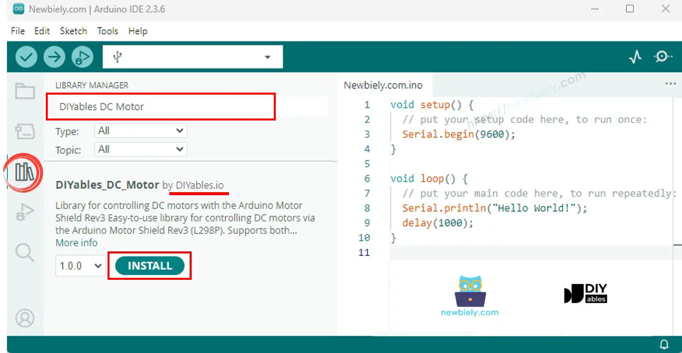
- Navigate to the Libraries icon on the left bar of the Arduino IDE.
- Search "DIYables_DC_Motor", then find the DIYables_DC_Motor library by DIYables.
- Click Install button to install the latest version of the library.
Note: This library is self-contained with no external dependencies.
Basic Structure
Every sketch using the DC Motor library follows this basic structure:
motor.begin() initializes the direction, PWM, and brake pins. After that, use motor.run() to set direction and speed, and motor.brake() to stop the motor. No loop() call on the motor object is needed - the motor runs continuously until you change its state.
Arduino Code - Channel A Motor Control
The following code demonstrates how to control a DC motor on Channel A: alternating direction every 2 seconds with braking in between.
Quick Steps
- Mount the Motor Shield Rev3 on the Arduino board.
- Connect the DC motor to Channel A screw terminals.
- Connect the external power source.
- Connect the Arduino board to your computer with a USB cable.
- Open Arduino IDE, select the right board and port.
- Copy the above code and paste it to the editor of Arduino IDE.
- Click Upload button on Arduino IDE to upload code to Arduino.
- Open the Serial Monitor to see the motor status messages.
The motor spins forward for 2 seconds at speed 30, brakes for 2 seconds, then spins backward for 2 seconds, and repeats.
Motor API Summary
| Method | Description | Example |
|---|---|---|
| run(direction, speed) | Set direction and speed, release brake | motor.run(MOTOR_FORWARD, 100) |
| setSpeed(speed) | Set PWM speed (0-255) | motor.setSpeed(150) |
| setDirection(direction) | Set direction only | motor.setDirection(MOTOR_BACKWARD) |
| brake() | Activate brake and set speed to 0 | motor.brake() |
| release() | Release brake | motor.release() |
| readCurrent() | Read raw ADC from current sensing pin | motor.readCurrent() |
Arduino Code - Channel B Motor Control
The following code demonstrates how to control a DC motor on Channel B.
Quick Steps
- Connect the DC motor to Channel B screw terminals (instead of Channel A).
- Copy the above code and paste it to the editor of Arduino IDE.
- Click Upload button on Arduino IDE to upload code to Arduino.
- Open the Serial Monitor.
The behavior is identical to Channel A - the only difference is the channel used.
Arduino Code - Both Channels
The following code demonstrates how to control two DC motors simultaneously, one on each channel.
Quick Steps
- Connect one DC motor to Channel A and another to Channel B.
- Copy the above code and paste it to the editor of Arduino IDE.
- Click Upload button on Arduino IDE to upload code to Arduino.
- Open the Serial Monitor.
Both motors run forward together, then backward together, then in opposite directions - with braking pauses in between.
Arduino Code - Current Sensing
The following code demonstrates how to read the current drawn by a DC motor using the built-in current sensing pin.
Quick Steps
- Connect a DC motor to Channel A.
- Copy the above code and paste it to the editor of Arduino IDE.
- Click Upload button on Arduino IDE to upload code to Arduino.
- Open the Serial Monitor.
- Observe the raw ADC current sensing value updating every 500 ms.
Current Sensing Notes
The Motor Shield Rev3 provides current sensing through analog pins A0 (Channel A) and A1 (Channel B). The readCurrent() method returns a raw ADC value. To convert to actual current (in amps), you need to apply the appropriate conversion factor based on the shield's current sensing circuitry.
Arduino Code - Custom Pins
The following code demonstrates how to create a motor object with custom pin assignments instead of using the predefined channel constants.
Quick Steps
- Adjust the pin numbers in the constructor to match your wiring.
- Copy the above code and paste it to the editor of Arduino IDE.
- Click Upload button on Arduino IDE to upload code to Arduino.
This approach is useful when using a non-standard motor driver or a modified pin configuration.
Troubleshoot
If the code is not working, there are some common issues you can troubleshoot:
- Motor not spinning: Check that the motor is properly connected to the correct channel's screw terminals.
- Wrong channel: Make sure the pin definitions in your code match the channel you connected the motor to (Channel A or Channel B).
- No power: Verify that the external power source is connected and working. The motor needs external power - USB alone is not enough for motor operation.
- Weak or no rotation: Increase the speed value in setSpeed() or run(). A very low speed (e.g., below 20) may not be enough to overcome the motor's starting torque.
- Direction reversed: Simply swap the two motor wires on the screw terminal, or change MOTOR_FORWARD to MOTOR_BACKWARD in your code.
Arduino DC Motor Shield - Full Demo
The below is a step-by-step video tutorial demonstrating all examples of the DC Motor Shield:
Platform Support
The library uses only Arduino standard APIs (pinMode, digitalWrite, analogWrite, analogRead) and supports all Arduino platforms (architectures=*).