
Arduino - MAX6675 Thermocouple Module
Say you want to check how hot a soldering iron tip really gets, keep an eye on the inside of a toaster oven while it's baking, or log the flue temperature on a wood stove. The DS18B20 and DHT-series sensors covered in our other tutorials are rated for maybe 125°C at the very most - nowhere near enough for jobs like these, and pushing them past their limit will just kill the chip.
That's exactly where a thermocouple comes in. In this tutorial, you'll wire up a MAX6675 thermocouple module - a cheap, easy-to-find breakout that pairs with a Type-K thermocouple probe - to an Arduino, and read live temperature values on the Serial Monitor.
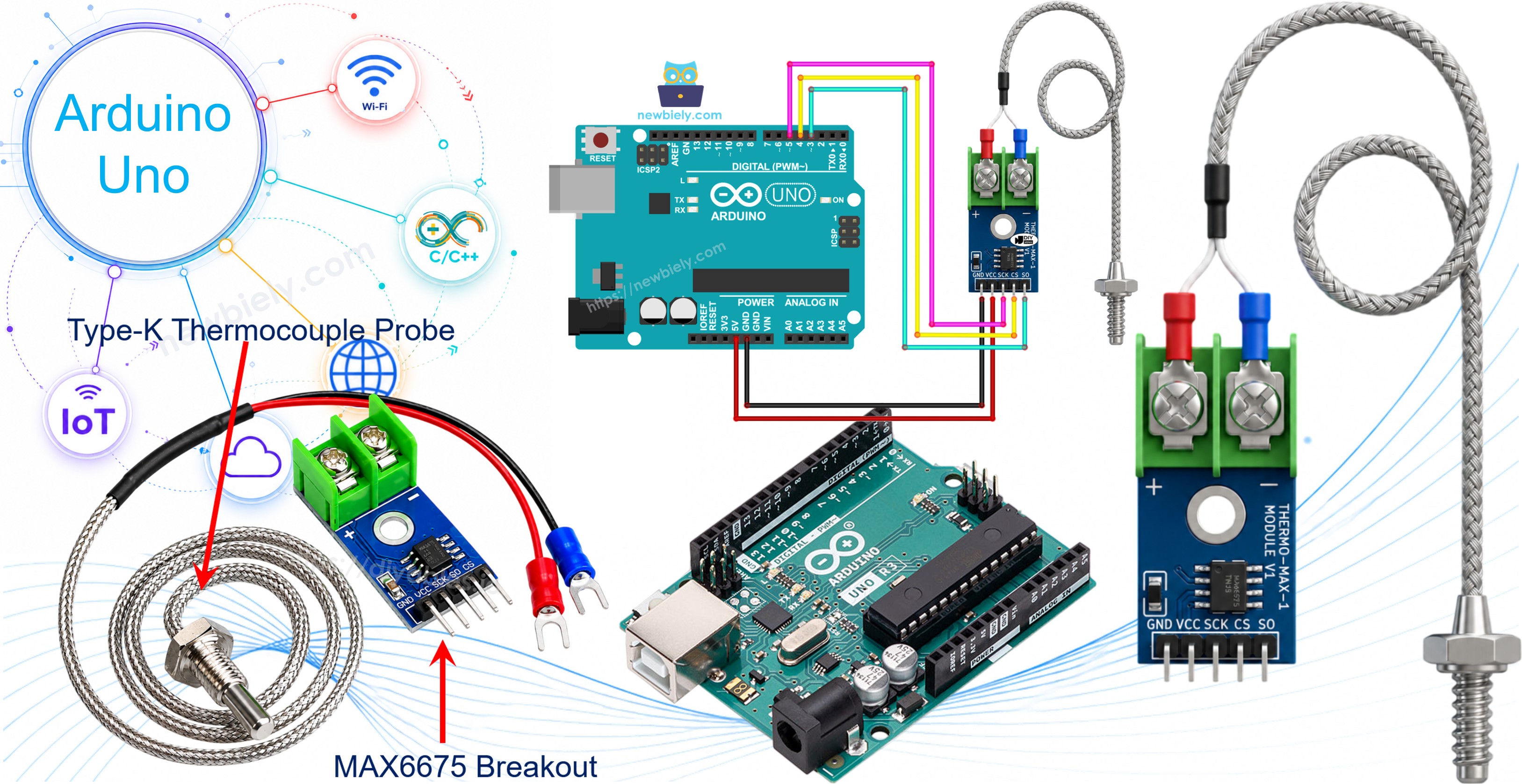
Hardware Required
Or you can buy the following kits:
| 1 | × | DIYables STEM V3 Starter Kit (Arduino included) | |
| 1 | × | DIYables Sensor Kit (18 sensors/displays) |
Additionally, some links direct to products from our own brand, DIYables .
What Makes a Thermocouple Different
A thermocouple is nothing more than two different metal wires twisted or welded together at one end. That joined end - the hot junction - produces a tiny voltage once it's heated, and that voltage rises and falls with the temperature. Because there's no fragile circuitry sitting at the hot end, just plain metal wire, a thermocouple can shrug off heat that would instantly cook a normal electronic sensor.
The most common variety is the Type-K thermocouple, made from a pair of Chromel and Alumel wires. It's cheap, widely available, and can measure across a huge span - roughly -328°F up to +2300°F. The one catch is that its output signal is only a few millivolts, far too small to read directly, so a dedicated chip is needed to turn that whisper of a voltage into a real temperature reading. That chip is the MAX6675.
About the MAX6675 Module
What you'll actually buy is a small breakout board built around the MAX6675 chip, sold together with a Type-K thermocouple probe.
MAX6675 Module Pinout
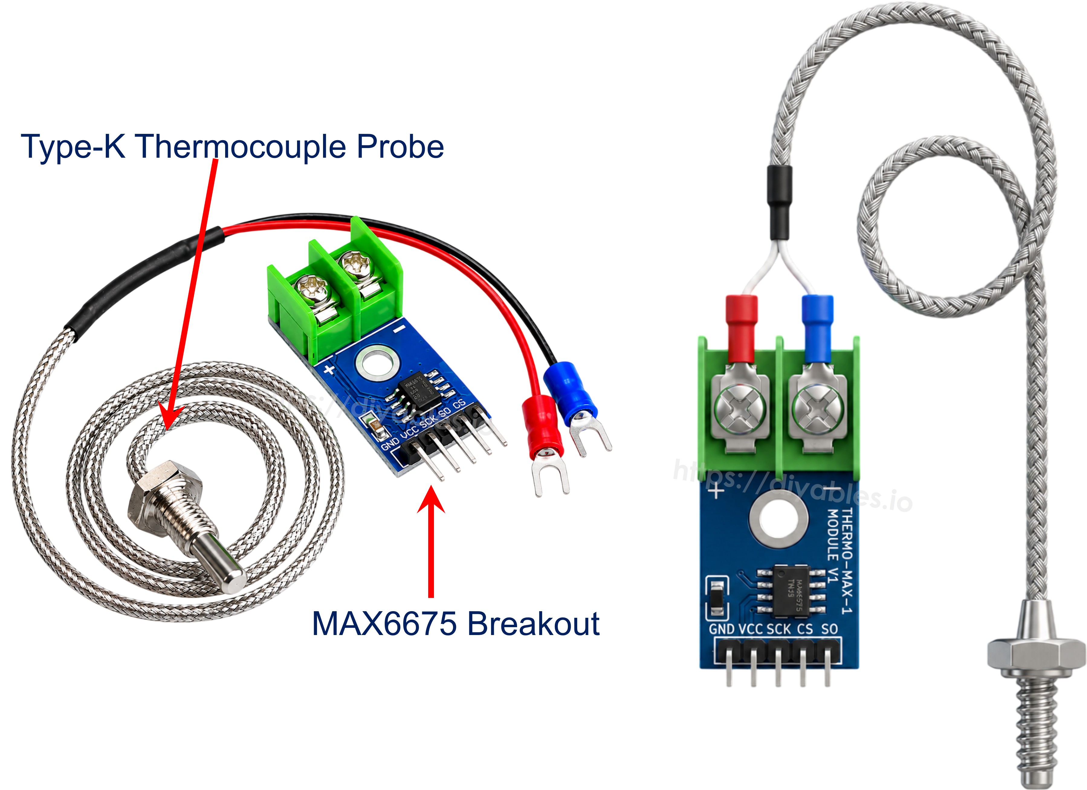
The board samples the probe's voltage, digitizes it with a 12-bit ADC, and hands the reading to the Arduino over a plain 3-wire link. Since the Arduino only ever needs to pull data out of the chip, there's no MOSI pin - just:
- VCC: power pin, works anywhere from 3.0V to 5.5V.
- GND: ground pin.
- SCK: clock line driven by the Arduino to shift each reading out of the chip.
- CS: chip select, held low while a reading is being taken.
- SO: serial data output - this is the module's read-only data line, carrying the 12-bit reading back to the Arduino.
Facing the opposite edge of the board is a small 2-pin terminal block for the probe itself: the red wire lands in the + slot, the blue wire in the - slot.
The bundled probe is about 18 inches of cable and is only rated from 0°C to 80°C, even though the MAX6675 chip behind it can digitize readings anywhere from 0°C to 1024°C. If a project needs to read hotter than 80°C, you'd pair this same breakout with a separately-sold, higher-temperature Type-K probe instead of the one included in the box.
A few more numbers worth knowing:
- Operating Voltage: 3.0V to 5.5V
- Measurable Range: 0°C to 1024°C (bundled probe capped at 80°C)
- Accuracy: ±3°C
- Resolution: about 0.25°C
Wiring Diagram
Wire the module's VCC pin to the Arduino's 5V pin and GND to GND, then pick any three spare digital pins for SCK, CS, and SO. Finally, seat the thermocouple probe's red and blue wires into the module's + and - terminal block.
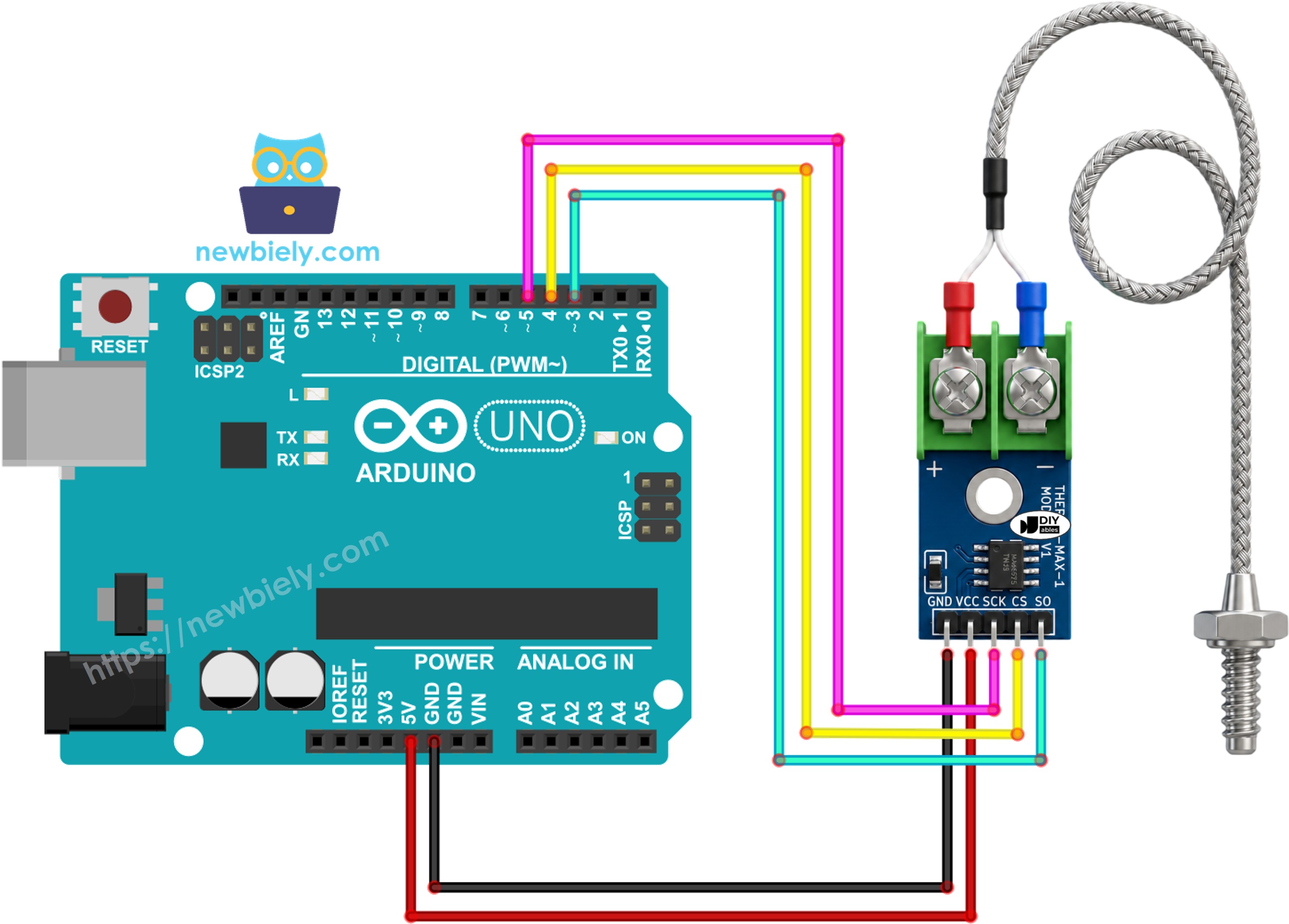
This image is created using Fritzing. Click to enlarge image
Wiring table of MAX6675 Module and Arduino Uno
| MAX6675 Module | Arduino Uno |
|---|---|
| VCC | → 5V |
| GND | → GND |
| SCK | → 5 |
| CS | → 4 |
| SO | → 3 |
Arduino Code
Quick Steps
- Wire the MAX6675 module to the Arduino Uno following the table and diagram above.
- Clip the thermocouple probe's red (+) and blue (-) wires into the module's terminal block, if you haven't already.
- Connect the Arduino Uno to your computer with a USB cable.
- Open the Arduino IDE, then select the correct board and port.
- Click the Libraries icon on the left sidebar of the Arduino IDE.
- Search "MAX6675" and find the library published by Adafruit.
- Click the Install button to add it.
- Search for MAX6675 library created by Adafruit and click the Install button.
- Copy the code above and open it in the Arduino IDE.
- Click the Upload button to send the sketch to the Arduino Uno.
- Press the probe tip against something warm, or hold it in your hand.
- Open the Serial Monitor and watch the readings come in.
※ NOTE THAT:
If the Serial Monitor shows a frozen or clearly wrong value, double check that SCK, CS, and SO are wired to the exact pins used in the sketch, and make sure the probe's + and - wires are seated firmly in the terminal block rather than just resting in it.
Code Explanation
The sketch starts by pulling in the MAX6675 library, which takes care of the low-level communication with the chip.
Right after that, three pins are defined for the Arduino side of the connection - clock, chip select, and serial data out - matching whatever pins you wired in the previous section.
A MAX6675 object named thermocouple is then created, telling the library which pin does which job.
Inside setup(), only the serial connection needs to be opened, along with a short delay to let the module settle before it's asked for its first reading.
Inside loop(), two library functions do all the real work: readCelsius() and readFahrenheit() each trigger a fresh conversion on the chip and return the result in the requested unit.
Both values are then printed on a single line of the Serial Monitor, followed by a one-second pause before the loop repeats.
That one-second pause is comfortably longer than the roughly 220 milliseconds the MAX6675 needs to complete a single conversion internally, so the Arduino is never left waiting on a reading that isn't ready yet.
Video Tutorial
We are considering to make the video tutorials. If you think the video tutorials are essential, please subscribe to our YouTube channel to give us motivation for making the videos.