
Arduino - 10 Segment LED Bar Graph
In this tutorial, we are going to learn:
- How to connect 10 Segment LED Bar Graph to Arduino
- How to program Arduino to control the 10 Segment LED Bar Graph
Hardware Required
Or you can buy the following kits:
| 1 | × | DIYables STEM V3 Starter Kit (Arduino included) | |
| 1 | × | DIYables Sensor Kit (18 sensors/displays) |
Disclosure: Some links in this section are Amazon affiliate links. If you make a purchase through these links, we may earn a commission at no extra cost to you.
Additionally, some links direct to products from our own brand, DIYables .
Additionally, some links direct to products from our own brand, DIYables .
About 10 Segment LED Bar Graph
| 10 Segment LED Bar Graph | |
|---|---|
| Number of Segments | 10 |
| LED Color | Bright red |
| Forward Voltage | ~2V per segment |
| Forward Current | 20mA max per segment |
| Resistor Required | 220Ω per segment |
Pinout
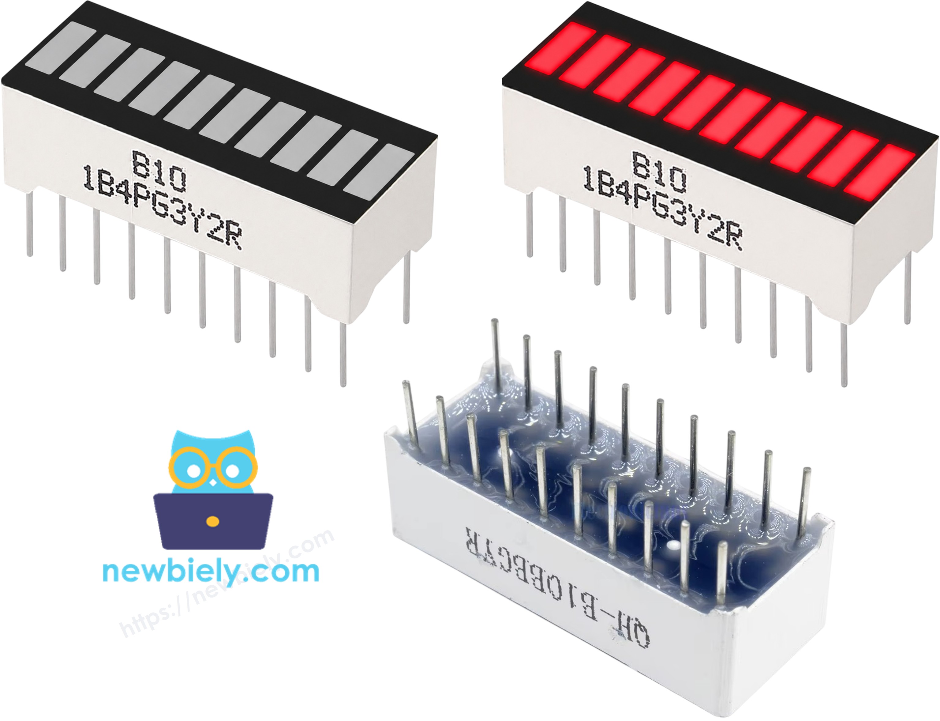
- Anode pins (A1–A10): each needs to be connected to a GPIO pin via a 220Ω resistor
- Cathode pins (K1–K10): each needs to be connected to GND
Wiring Diagram
Connect the 10 Segment LED Bar Graph to Arduino Uno as shown in the table below.
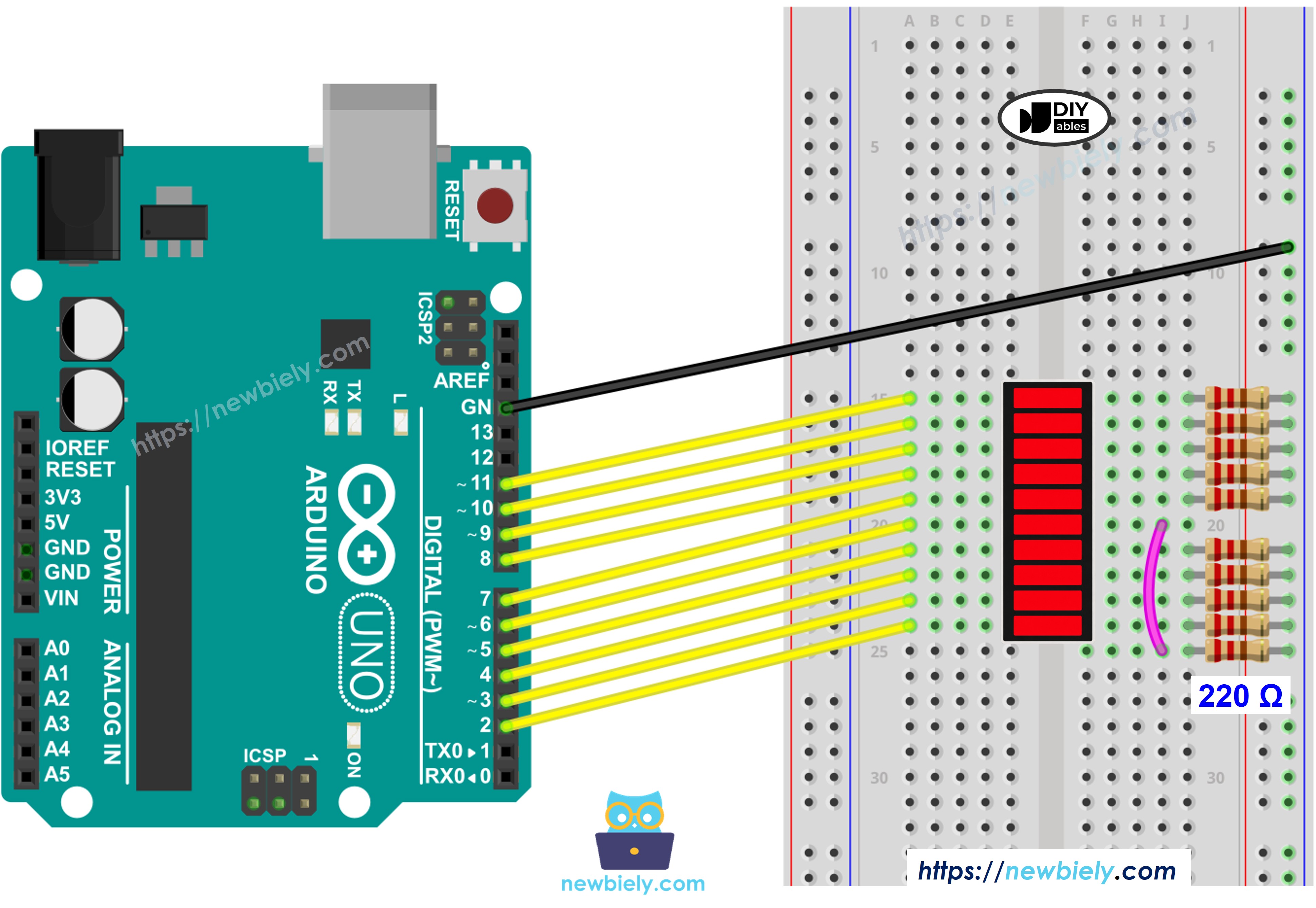
This image is created using Fritzing. Click to enlarge image
| LED Bar Graph | Arduino Pin |
|---|---|
| A1 (Anode 1) | Pin 2 (via 220Ω) |
| A2 (Anode 2) | Pin 3 (via 220Ω) |
| A3 (Anode 3) | Pin 4 (via 220Ω) |
| A4 (Anode 4) | Pin 5 (via 220Ω) |
| A5 (Anode 5) | Pin 6 (via 220Ω) |
| A6 (Anode 6) | Pin 7 (via 220Ω) |
| A7 (Anode 7) | Pin 8 (via 220Ω) |
| A8 (Anode 8) | Pin 9 (via 220Ω) |
| A9 (Anode 9) | Pin 10 (via 220Ω) |
| A10 (Anode 10) | Pin 11 (via 220Ω) |
| K1–K10 (Cathodes) | GND |
How To Program Arduino for 10 Segment LED Bar Graph
- No library needed: LED Bar Graph uses only the built-in digitalWrite() function
- Define pins: const int ledPins[10] = {2, 3, 4, 5, 6, 7, 8, 9, 10, 11};
- Set each pin as output: pinMode(ledPins[i], OUTPUT);
- Light a segment: digitalWrite(ledPins[i], HIGH);
- Turn off a segment: digitalWrite(ledPins[i], LOW);
- Print bar state: iterate the array, print * for lit segments and for off segments
Arduino Code - 10 Segment LED Bar Graph
Quick Steps
- Connect Arduino to PC via USB cable.
- Navigate to the Tools menu, select the right board and port.
- Copy the above code and paste it to Arduino IDE.
- Click Upload button on Arduino IDE to upload code to Arduino.
- Observe the LED bar graph fill up segment by segment then empty back down in a repeating animation.
/*
* Created by ArduinoGetStarted.com
*
* This example code is in the public domain
*
* Tutorial page: https://arduinogetstarted.com/tutorials/arduino-10-segment-led-bar-graph
*/
const int NUM_SEGMENTS = 10;
const int ledPins[NUM_SEGMENTS] = {2, 3, 4, 5, 6, 7, 8, 9, 10, 11};
void printBar(int litCount) {
Serial.print("Bar: [");
for (int i = 0; i < NUM_SEGMENTS; i++) {
Serial.print(i < litCount ? "*" : " ");
}
Serial.println("]");
}
void setup() {
Serial.begin(9600);
for (int i = 0; i < NUM_SEGMENTS; i++) {
pinMode(ledPins[i], OUTPUT);
digitalWrite(ledPins[i], LOW);
}
}
void loop() {
for (int i = 0; i < NUM_SEGMENTS; i++) {
digitalWrite(ledPins[i], HIGH);
printBar(i + 1);
delay(100);
}
delay(500);
for (int i = NUM_SEGMENTS - 1; i >= 0; i--) {
digitalWrite(ledPins[i], LOW);
printBar(i);
delay(100);
}
delay(500);
}
Serial Monitor Output
8
Serial.println("Hello World!");
Message (Enter to send message to 'Arduino Uno' on 'COM15')
New Line
9600 baud
Bar: [* ]
Bar: [** ]
Bar: [*** ]
Bar: [**** ]
Bar: [***** ]
Bar: [****** ]
Bar: [******* ]
Bar: [******** ]
Bar: [********* ]
Bar: [**********]
Bar: [********* ]
Bar: [******** ]
Bar: [******* ]
Bar: [****** ]
Bar: [***** ]
Bar: [**** ]
Bar: [*** ]
Bar: [** ]
Bar: [* ]
Bar: [ ]
Video Tutorial
We are considering to make the video tutorials. If you think the video tutorials are essential, please subscribe to our YouTube channel to give us motivation for making the videos.