
Arduino - NTC Thermistor Temperature Sensor
A thermistor probe is one of the cheapest ways to give a project a real thermometer, and this one is sealed in steel, so it can sit in a fish tank or a cup of tea. In this tutorial, we are going to learn:
- What a 10K NTC thermistor is, and why its resistance drops when it gets warmer
- How to connect the waterproof probe and its 10K resistor to Arduino Uno
- How to program Arduino to turn the analogRead() value into ohms, °C and °F
- How to let the code tell you when the probe is unplugged or shorted
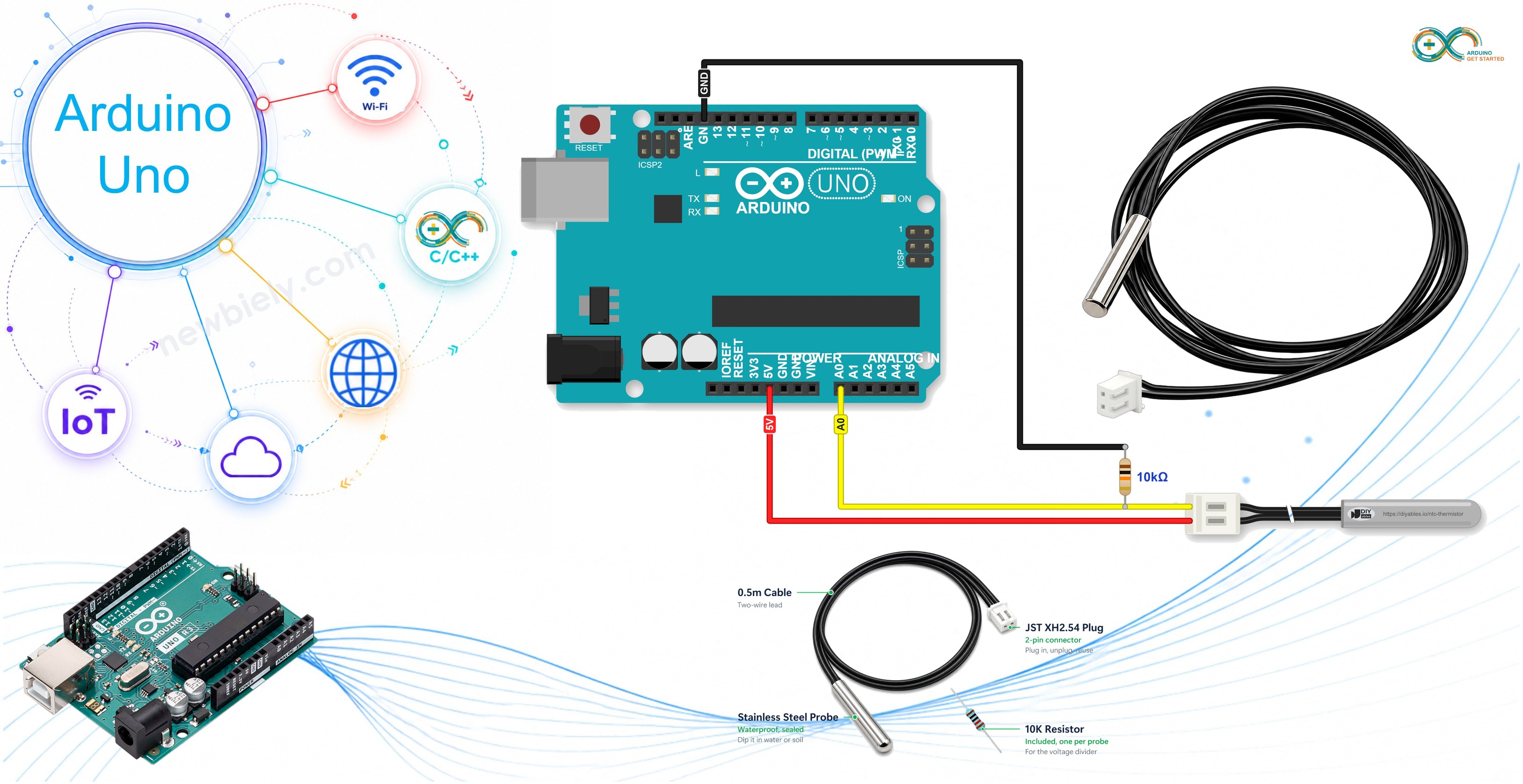
Hardware Required
Or you can buy the following kits:
| 1 | × | DIYables STEM V3 Starter Kit (Arduino included) | |
| 1 | × | DIYables Sensor Kit (18 sensors/displays) |
Additionally, some links direct to products from our own brand, DIYables .
About NTC Thermistor Temperature Sensor
Put simply, a thermistor is a resistor that is very sensitive to heat. The letters "NTC" mean Negative Temperature Coefficient: the warmer it gets, the fewer ohms it has. Arduino finds those ohms and converts them into degrees.
The one in this tutorial is a 10K NTC thermistor with a B value of 3950, the most common type for hobby projects. It is hidden inside a small stainless steel tube with a round tip, on a 0.5m black cable. The kit has five probes and five matching 10K resistors, so you do not need to buy the resistor separately.
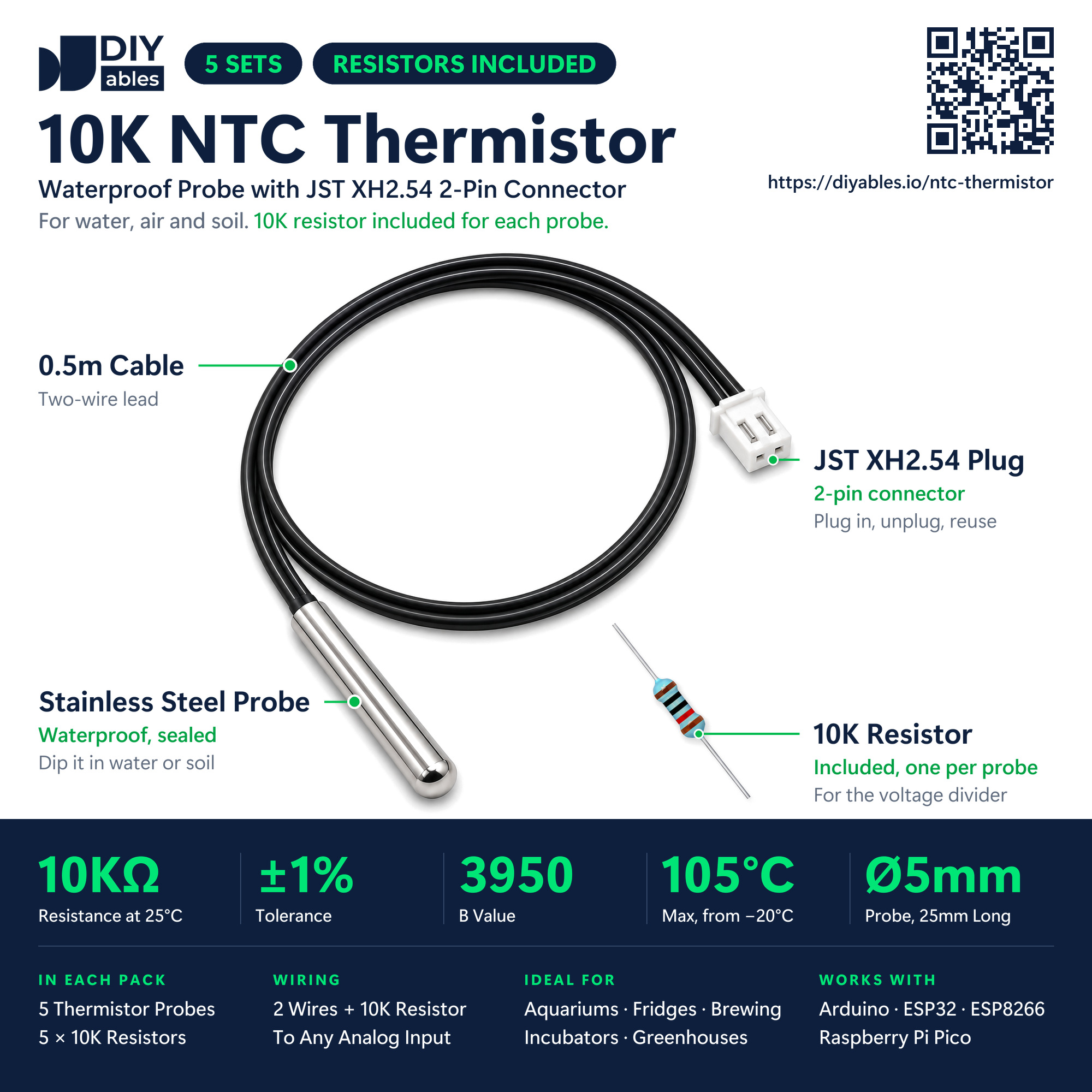
The cable has only two wires, and they end in a white JST XH2.54 2-pin plug. There is no adapter board. Just push two male jumper wires into the two holes of the plug. A thermistor has no + or - side, so it does not matter which wire is which:
- Wire 1: needs to be connected to the 5V pin of the Arduino Uno
- Wire 2: needs to be connected to an analog input pin (A0 in this tutorial)
- 10K resistor: needs to be connected between that analog pin and GND (0V)
| 10K NTC Thermistor Probe | |
|---|---|
| Thermistor Type | NTC, 10kΩ at 25°C, ±1% |
| B Value | 3950 |
| Measuring Range | -20°C to 105°C |
| Probe | stainless steel, waterproof, 5mm x 25mm, round tip |
| Cable | 0.5m, two wires |
| Connector | JST XH2.54 2-pin plug |
| Dissipation Constant | 5mW/°C (typical) |
| Output | resistance (needs the 10K resistor and an analog input) |
From Ohms to Degrees
Arduino cannot measure a resistance directly. It can only measure a voltage. So the thermistor and the 10K resistor are joined in series between 5V and GND, and the point between them goes to A0. This is called a voltage divider. When the probe gets warmer, its resistance falls, a bigger part of the 5V reaches A0, and analogRead() returns a bigger number.
| Temperature | Thermistor | Voltage on A0 | analogRead() |
|---|---|---|---|
| 0°C | 33.6kΩ | 1.15V | 235 |
| 10°C | 20.2kΩ | 1.66V | 339 |
| 25°C | 10.0kΩ | 2.50V | 512 |
| 50°C | 3.6kΩ | 3.68V | 753 |
| 100°C | 0.7kΩ | 4.67V | 956 |
The code goes the other way. From the ADC value it first finds the thermistor resistance R. Then the B formula (also called the beta equation) gives the temperature T in kelvin:
1/T = 1/T0 + (1/B) × ln(R/R0)
Here T0 = 298.15K (25°C), R0 = 10000Ω and B = 3950. Subtract 273.15 from T to get °C. Some tutorials use the Steinhart-Hart equation, which takes three coefficients; since DIYables gives this probe's B value (3950), one coefficient is enough. Expect the Uno to agree with a kitchen thermometer to about 1°C near room temperature. The small difference that is left comes from the 10K resistor and from the Arduino's ADC.
Why does wire 1 go to 5V and not to 3.3V? The Uno's ADC compares the voltage on A0 with its own 5V supply. When the divider gets the same 5V, only the ratio between the two counts. Say your USB port only delivers 4.85V: the divider output and the ADC reference drop by the same share, so the ratio, and the temperature, stay put. This is why the code never needs to know the exact supply voltage.
Wiring Diagram
One thermistor wire goes to 5V, the other goes to A0, and the 10K resistor connects A0 to GND. A small breadboard makes the meeting point of the A0 wire, the resistor and the GND wire easy to build. You can also twist or solder the resistor legs to the wires.
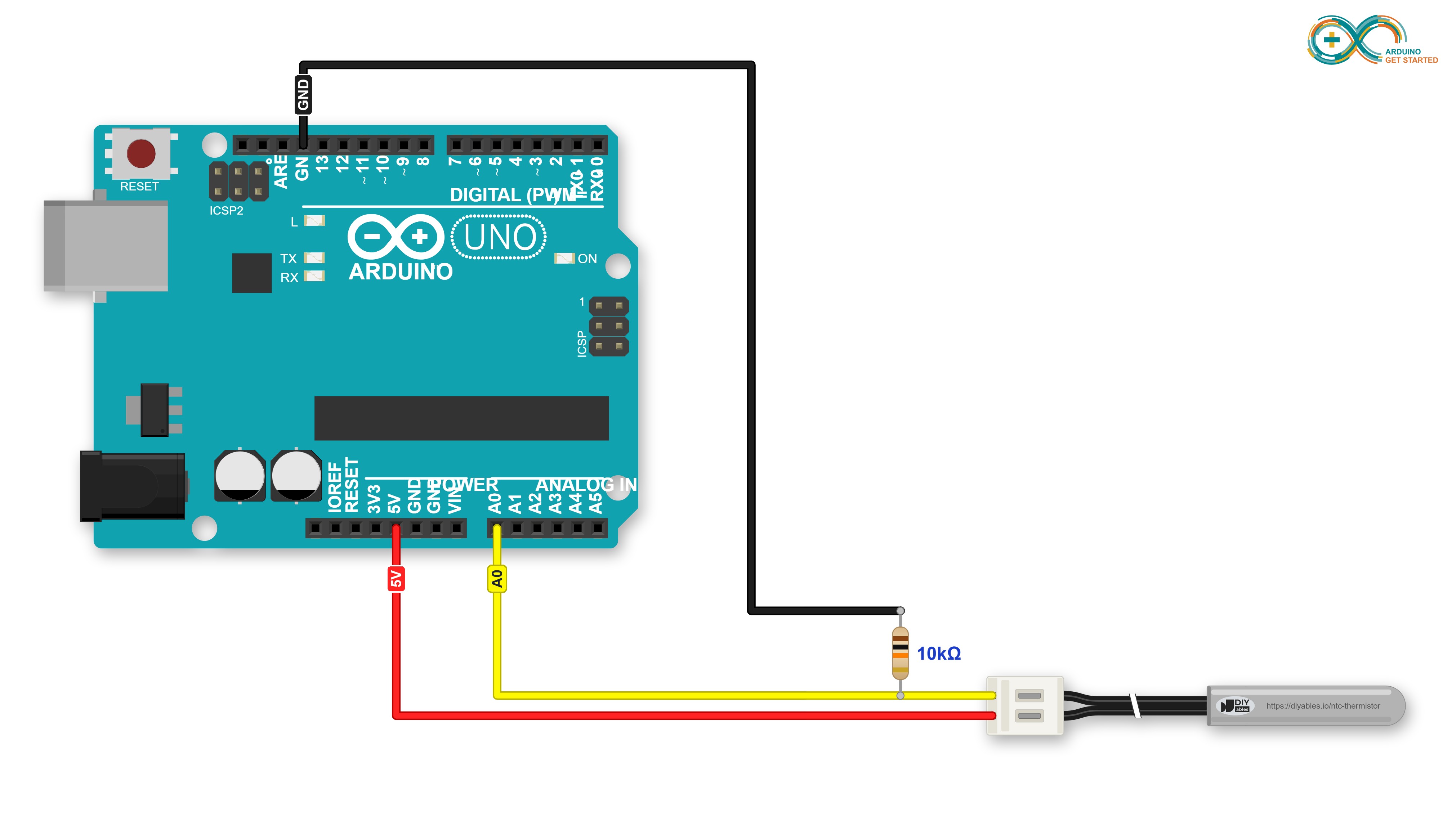
This image is created using Fritzing. Click to enlarge image
| NTC Thermistor Circuit | Arduino Uno Pin |
|---|---|
| Probe wire 1 (either wire) | 5V |
| Probe wire 2 | A0 |
| 10K resistor, first leg | A0 |
| 10K resistor, second leg | GND |
Jumper wires can come loose when you move the project. You can stack a Proto Screw Terminal Block Shield or a Screw Shield V2 on the Arduino and connect the wires to its screw terminals. The diagram below shows the same wiring with the Screw Shield V2.
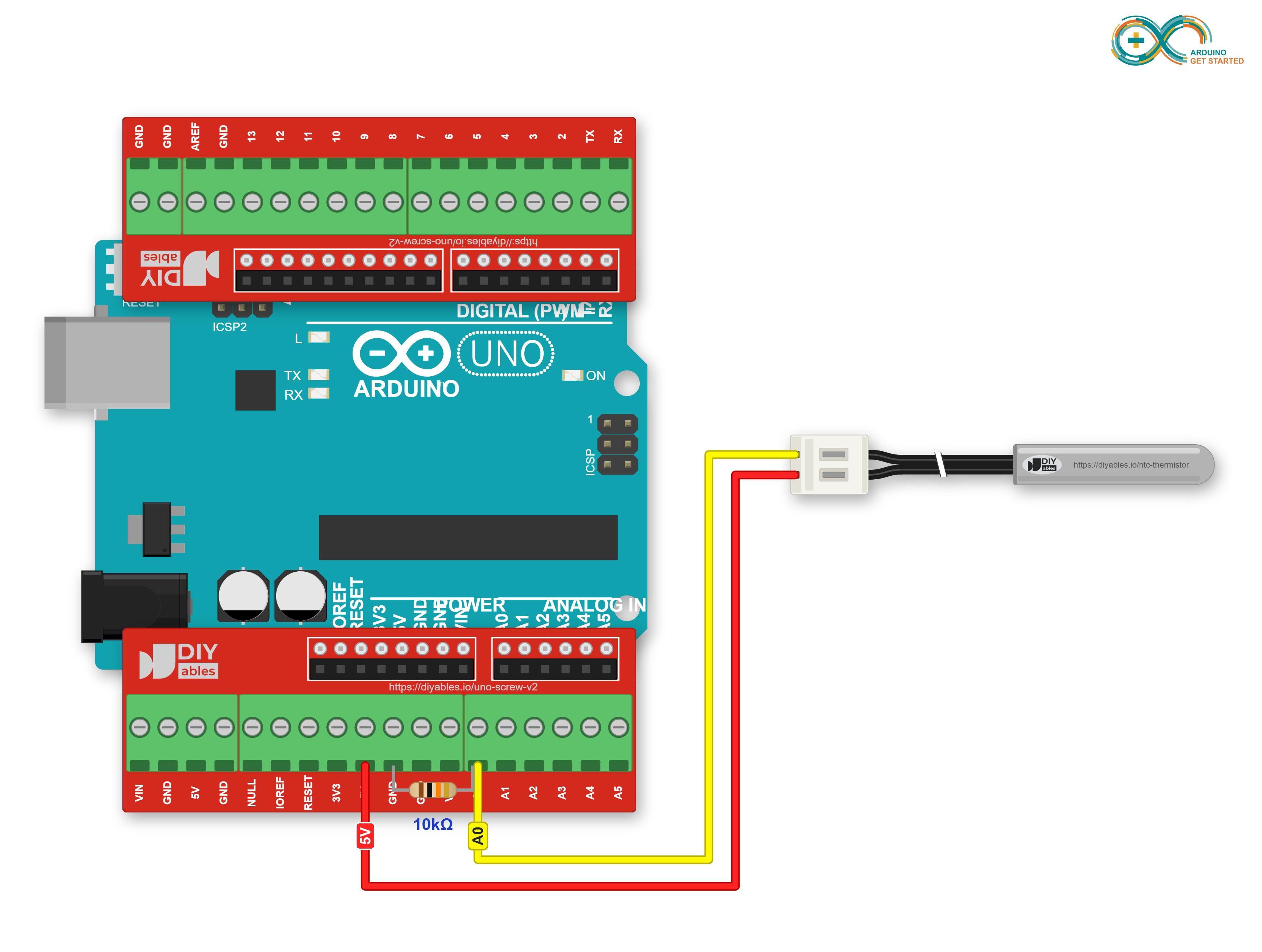
This image is created using Fritzing. Click to enlarge image
On the screw shield, the 10K resistor needs no extra wire: one leg goes into a GND terminal, and the other leg shares the A0 terminal with the probe wire. Tighten each screw over both.
※ NOTE THAT:
- Water is fine for the steel tip only. The white plug and the spot where the resistor joins the wires must stay dry.
- Do not move wire 1 to the 3.3V pin. The Uno's ADC still measures against 5V, so every reading would come out wrong.
- Never put the probe in anything hotter than 105°C.
How To Program For NTC Thermistor
- No library is needed. Define the analog pin and the numbers of the thermistor:
- Read A0 ten times and take the average. A single reading jumps a little, and the average is calmer:
- Find the thermistor resistance from the ADC value. Because the thermistor is on the 5V side of the divider, the formula is:
- Use the B formula to get kelvin, then Celsius and Fahrenheit. In C++, log() is the natural logarithm (ln):
- Check the ADC value before the math. A value near 0 means the probe is not plugged in (the resistor pulls A0 to GND). A value near 1023 means a short or a missing resistor. Without this check, the sketch would print strange numbers such as inf or nan.
Arduino Code - NTC Thermistor Temperature Sensor
Once per second, the sketch prints the averaged ADC value, the thermistor resistance, and the temperature in °C and °F. If the probe is unplugged or shorted, it prints a warning instead.
Quick Steps
- Connect Arduino to PC via USB cable.
- Wire the thermistor probe and the 10K resistor to Arduino as shown in the wiring diagram.
- Open Arduino IDE, select the right board and port.
- Copy the above code and paste it to Arduino IDE.
- Click Upload button on Arduino IDE to upload code to Arduino.
- Open the Serial Monitor and set the baud rate to 9600.
- Fill a glass with ice and a little water, and stir it. Leave the probe in the air for a few lines, then put the steel tip into the ice water.
The first three lines are the air in the room. When the tip went into the ice water, the resistance grew and the reading fell for about ten seconds before it settled. Stirred ice water is always close to 0°C, so it is an easy test for your probe: a result within about 1°C is normal.
If the temperature goes DOWN when you hold the probe in your hand, the thermistor and the 10K resistor have changed places. Put the thermistor on the 5V side and the resistor on the GND side, as in the wiring table.
Ideas for what to build next:
- A fridge or freezer alarm that beeps with a piezo buzzer when the inside gets warmer than a limit you choose.
- An aquarium heater control that switches the heater with a relay.
- A small thermometer for home brewing that shows the temperature on an LCD I2C.
Want a probe that sends a ready digital value, with no resistor and no formula? See Arduino - Temperature Sensor for the waterproof DS18B20. For an oven or a soldering iron, far above 105°C, use Arduino - MAX6675 Thermocouple Module.
Video Tutorial
We are considering to make the video tutorials. If you think the video tutorials are essential, please subscribe to our YouTube channel to give us motivation for making the videos.