
Arduino - BTS7960 Motor Driver
An Arduino Uno can be the brain of a sliding gate opener. The hard part is the 12V gear motor that drags the heavy gate: it pulls far more current than a small motor driver can give. The BTS7960 module is built for motors like this. In this tutorial, we are going to learn:
- What the BTS7960 motor driver is, and what each pin on its 8-pin header does
- How to connect the BTS7960, a 12V DC motor and a 12V power adapter to Arduino Uno
- How to program Arduino to set the speed and the direction of the motor with PWM
- How "brake" and "coast" stop the motor in two different ways
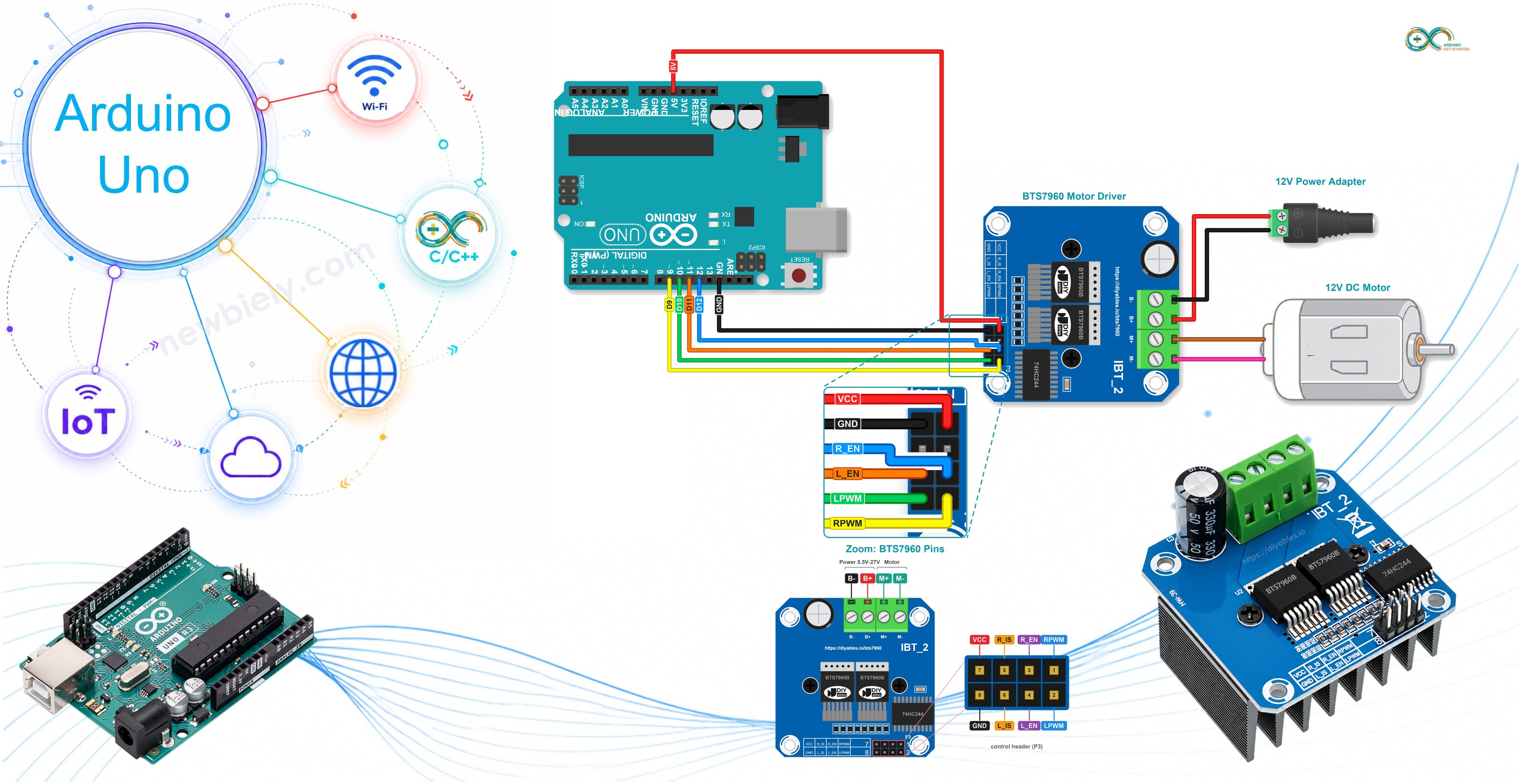
Hardware Required
Or you can buy the following kits:
| 1 | × | DIYables STEM V3 Starter Kit (Arduino included) | |
| 1 | × | DIYables Sensor Kit (18 sensors/displays) |
Additionally, some links direct to products from our own brand, DIYables .
Choose a 12V adapter that can give more current than your motor needs. The label of the motor, or its product page, tells you how much current that is.
About BTS7960 Motor Driver
The BTS7960 module is also sold as "IBT-2" or "HW-039". It carries two Infineon BTS7960B chips that share one big heat sink, bolted under the board. Each chip is a half-bridge, and the two halves together make one full H-bridge. So the module drives one brushed DC motor, forward or backward, and Arduino sets the speed with PWM. You can see it as the big brother of the L298N and the DRV8833. It is made for big gear motors, wiper motors, winches, scooters, wheelchair motors, heavy robots and, of course, gate openers.
| BTS7960 | |
|---|---|
| Driver Chips | 2 x Infineon BTS7960B (half-bridge), one full H-bridge |
| Motors | 1 brushed DC motor, both directions |
| Motor Supply (B+ and B-) | 5.5V to 27V DC (6V, 12V and 24V systems) |
| Current | up to 43A (current limit of the chip, for short peaks) |
| PWM Frequency | up to 25 kHz on RPWM and LPWM |
| Logic Supply (VCC) | 5V from Arduino, for the 74HC244 buffer chip only |
| Protection | current limiting, over-temperature |
How does it work, in short? Each BTS7960B chip can connect its motor wire either to B+ or to B-. When RPWM is HIGH, the right chip connects its wire to B+, while the left chip keeps the other wire on B-. The current then flows through the motor in one direction. LPWM does the same thing the other way around. With PWM, the pin turns on and off very fast, so the motor gets only a part of the power and turns slower.
The 43A in the table is the level where the chip starts to limit the current. It is not a value for long runs. For a motor that runs for minutes, keep the current far below 43A. The heat sink decides how much the board can carry for a long time.
Pinout
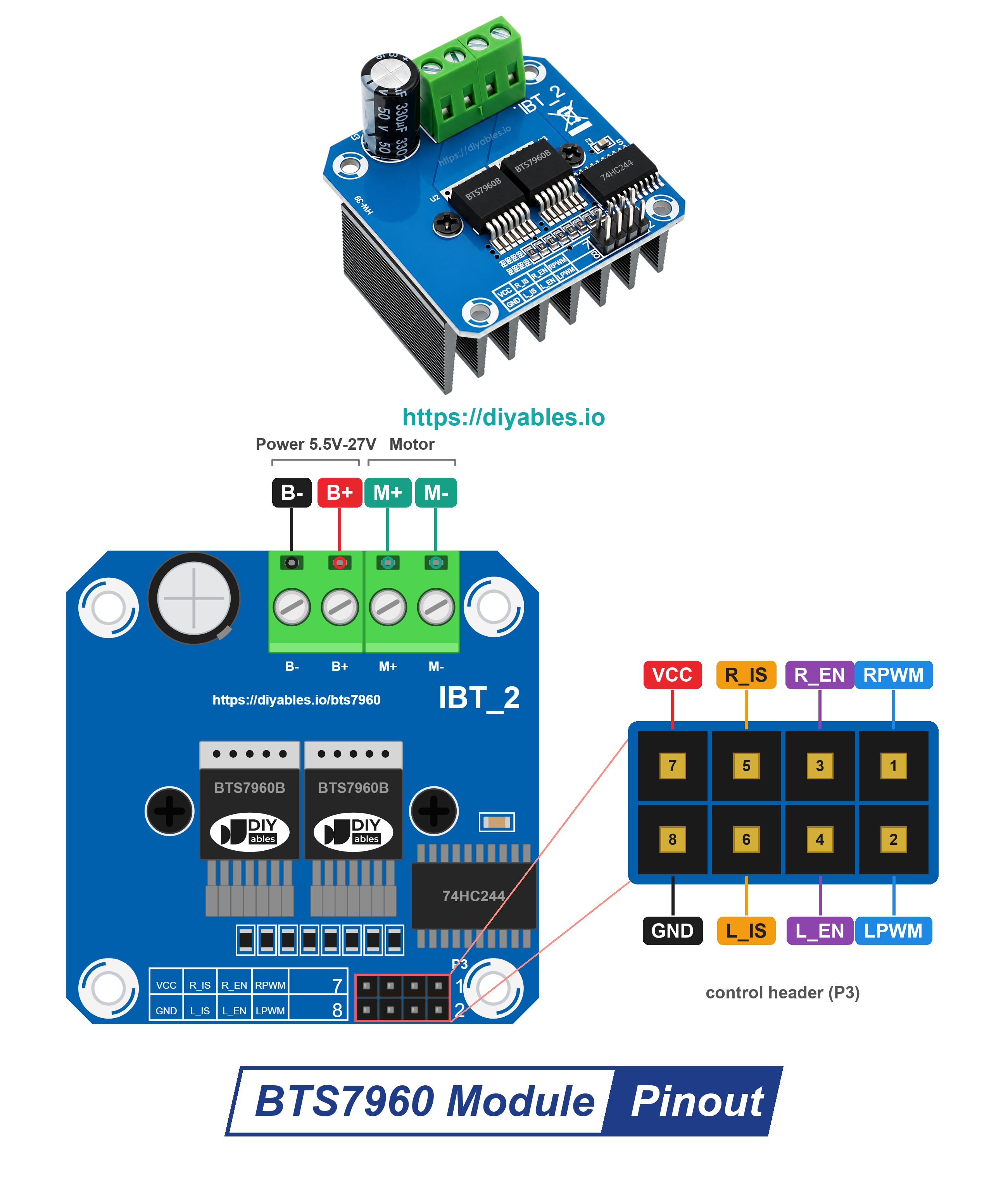
On one side, the module has a control header with 8 pins in two rows of 4. On the other side, it has a screw terminal for the power wires.
Control header:
- RPWM pin: needs to be connected to a PWM pin of Arduino. A PWM signal on this pin turns the motor forward (right half-bridge).
- LPWM pin: needs to be connected to another PWM pin of Arduino. A PWM signal on this pin turns the motor in reverse (left half-bridge).
- R_EN pin: needs to be HIGH to switch the right half-bridge on. LOW switches it off.
- L_EN pin: needs to be HIGH to switch the left half-bridge on. LOW switches it off.
- R_IS and L_IS pins: current sense and fault outputs. The board prints them as "R_S" and "L_S". We do not use them in this tutorial, so leave them unconnected.
- VCC pin: needs to be connected to 5V of Arduino. It powers only the 74HC244 buffer chip and the power LED, not the motor.
- GND pin: needs to be connected to GND of Arduino. On the module, this pin is joined to B-.
Screw terminal:
- B+ pin: needs to be connected to the positive (+) of the motor power supply (5.5V to 27V)
- B- pin: needs to be connected to the negative (-) of the motor power supply
- M+ and M- pins: the two wires of the DC motor
The 74HC244 buffer chip sits between the Arduino pins and the two power chips. The product page calls it the isolation chip. The Arduino pins only "talk" to this small chip, and the motor current never flows through them.
Speed, Direction, Brake and Coast
When R_EN and L_EN are both HIGH, the two PWM pins decide what the motor does:
| RPWM | LPWM | Motor | |
|---|---|---|---|
| PWM (0 to 255) | 0 | turns forward, a bigger value means a higher speed | |
| 0 | PWM (0 to 255) | turns in reverse, a bigger value means a higher speed | |
| 0 | 0 | brake | the driver joins the two motor wires together, so the motor stops fast |
When R_EN and L_EN are both LOW, both half-bridges are off. Nothing holds the motor, so it rolls on and stops by itself. This is called "coast".
A gate opener can use both stops: brake to stop the gate at the right spot, and coast to let it slow down softly.
※ NOTE THAT:
- Always keep one of RPWM and LPWM at 0. Never send PWM to both pins at the same time.
- The motor gets its power from the 12V adapter through B+ and B-, never from Arduino. Never connect B+ to any pin of Arduino.
- GND and B- are joined on the module. So the single GND wire from Arduino to the module also gives the common ground with the motor supply.
- Check + and - of the adapter before you plug it in. Wrong polarity can damage the module.
Wiring Diagram
Pins 9 and 10 of Arduino carry the PWM signals, pins 11 and 12 switch the two half-bridges, and 5V and GND power the buffer chip of the module.
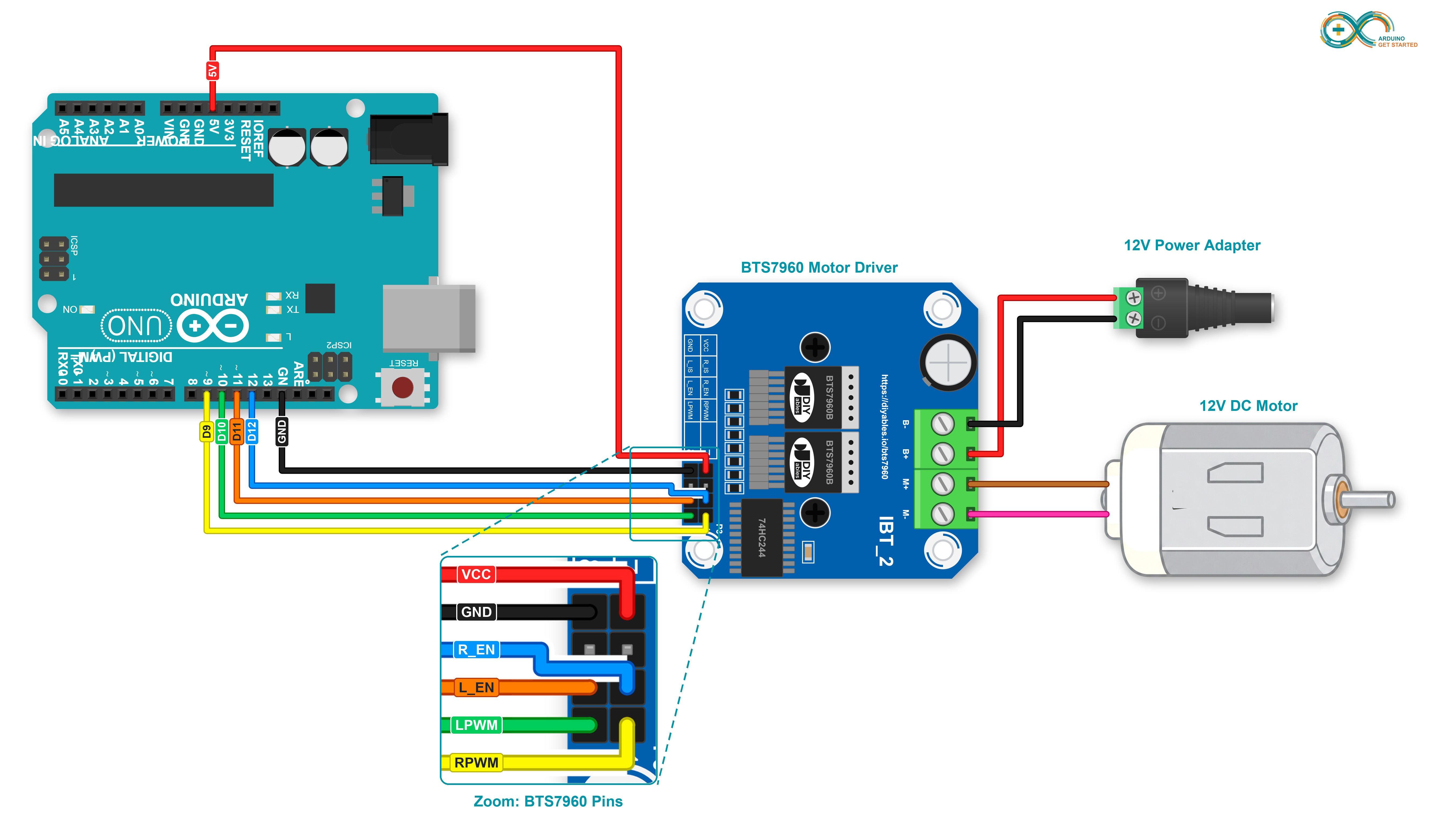
This image is created using Fritzing. Click to enlarge image
| BTS7960 Pin | Connect To |
|---|---|
| RPWM | Arduino pin 9 |
| LPWM | Arduino pin 10 |
| R_EN | Arduino pin 12 |
| L_EN | Arduino pin 11 |
| VCC | Arduino 5V |
| GND | Arduino GND |
| R_IS, L_IS | nothing (leave them free) |
| B+ | + of the 12V power adapter (through the DC power jack) |
| B- | - of the 12V power adapter (through the DC power jack) |
| M+, M- | the two wires of the 12V DC motor |
Jumper wires can come loose when you move the project. In this case, use a Proto Screw Terminal Block Shield or a Screw Shield V2. It plugs into the Arduino Uno and gives each pin a screw terminal. The wiring stays the same. Only the wires now go to the screw terminals, as shown below.
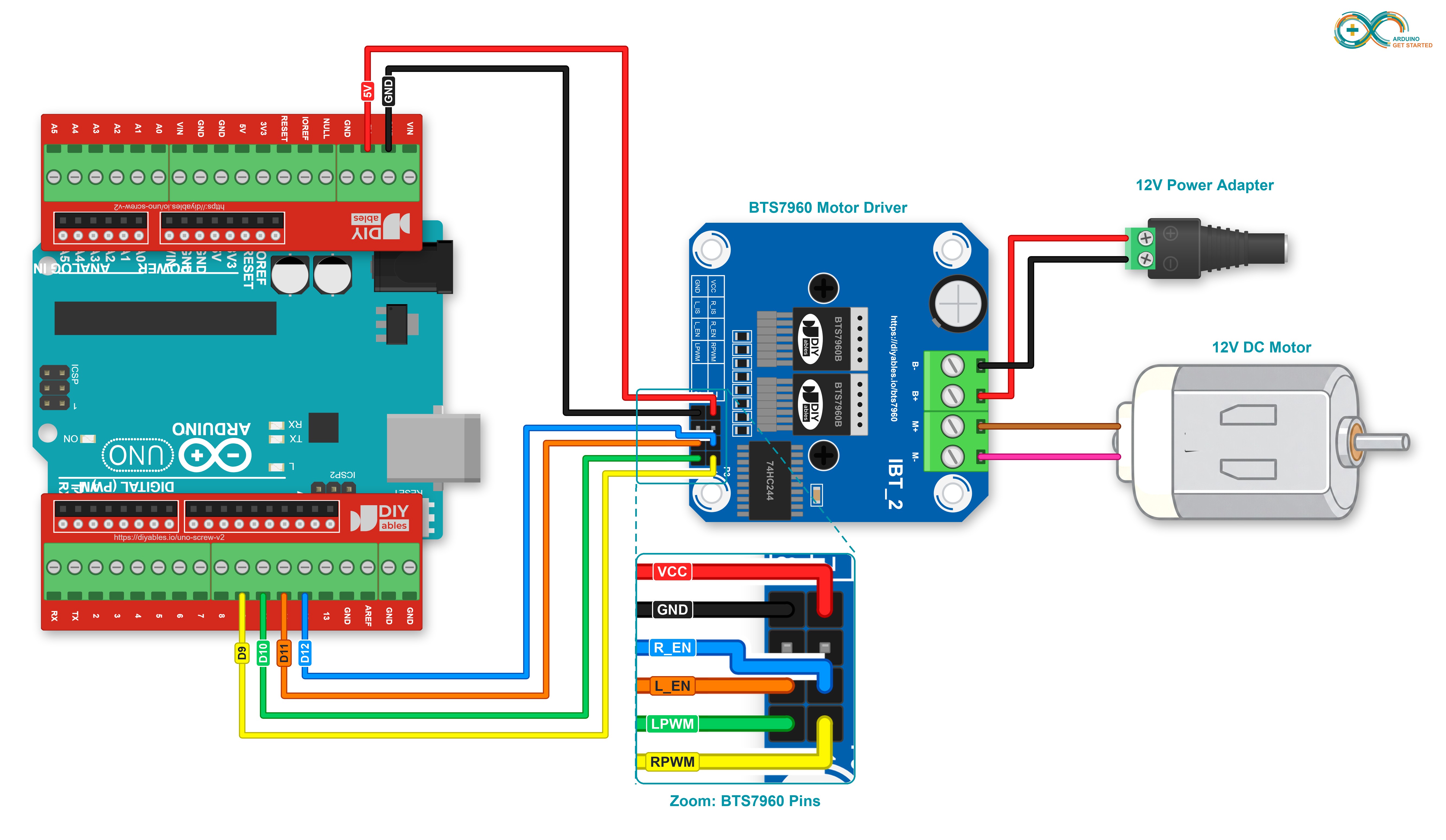
This image is created using Fritzing. Click to enlarge image
Look at the enable pins: R_EN goes to pin 12 and L_EN goes to pin 11. This order keeps the wires short and tidy. If you swap these two wires, the code still works, because the sketch always sets both enable pins at the same time.
How To Program For BTS7960 Motor Driver
- No library is needed. Define the four control pins:
- Set the four pins as outputs, put both PWM pins at 0, and then switch the driver on:
- Turn the motor forward. The speed is a number from 0 to 255:
- Turn the motor in reverse:
- Brake (the enable pins stay HIGH):
- Coast (switch both half-bridges off). Set the enable pins HIGH again before the next run:
Arduino Code - BTS7960 Motor Driver
The sketch takes the motor through six steps, and then starts again:
- Speeds up forward, from 0 to full speed
- Stays at full speed for 2 seconds
- Slows down to 0
- Brakes for 1 second
- Turns in reverse at about half speed for 2 seconds
- Coasts for 2 seconds with the driver off
Each step prints one line on the Serial Monitor.
Quick Steps
- Wire Arduino, the BTS7960 module, the motor and the DC power jack as shown in the wiring diagram. Keep the 12V adapter unplugged for now.
- Connect Arduino to PC via USB cable.
- Open Arduino IDE, select the right board and port.
- Copy the above code and paste it to Arduino IDE.
- Click Upload button on Arduino IDE to upload code to Arduino.
- Now plug the 12V power adapter into the DC power jack.
- Open the Serial Monitor, set the baud rate to 9600, and watch the motor.
- If the motor turns the wrong way (for example, the gate closes when it should open), swap the M+ and M- wires.
Watch steps [4] and [6]. In step [3] the speed already goes down to 0, so in step [4] the brake simply holds the motor still. In step [6] the driver turns off while the motor still turns in reverse. Now you can see the coast: the motor keeps turning for a short moment, and then it stops by itself.
At a low speed, the motor may hum or whine. This is normal. Pins 9 and 10 of Arduino Uno make PWM at about 490 Hz, and you can hear this frequency in the motor.
Ideas to turn this into a real gate opener:
- Stop the gate at each end with two limit switches. See Arduino - DC Motor - Limit Switch. That page uses the DRV8833, but the idea is the same.
- Open and close the gate with a remote control. See Arduino - IR Remote Control.
Is your motor small? Then the BTS7960 is more than you need. The Arduino - DRV8833 DC Motor Driver tutorial drives two small motors, and Arduino - DC Motor uses the DRV8833 too. The DRV8833 drives two motors at about 1.5A each, up to 10.8V. The BTS7960 drives only one motor, but with much more current and up to 27V.
Video Tutorial
We are considering to make the video tutorials. If you think the video tutorials are essential, please subscribe to our YouTube channel to give us motivation for making the videos.